MEGA CD Preservation
Introduction
Sega MegaCD's drive is the easiest part to broke and it's becoming more and more difficult to find a replacement part.
For homebrew developpers, it's also very difficult (and costly!) to burn CD-R at low speed for test, debug or release. (there is no more 1x CD burner on the market!)
There is so a real need to for an alternative.
This page focus on the Optical Drive Emulator alternative, like already seen on newer systems : WiiLoader, X360Dock, WODE, ...
But to develop an ODE for the MegaCD, you first should know what you have to emulate.
And, unfortunately, unlike newer systems based on IDE or another standard connection, the MegaCD uses its own.
This page aims to list all the informations needed to emulate the MegaCD drive at the hardware level.
There are several versions of the CD addon for Megadrive:
- Sega/MegaCD 1
- Sega/MegaCD 2 rev1
- Sega/MegaCD 2 rev2
- Sega/Victor WonderMega
- Victor WonderMega 2 / JVC X'Eye
- Sega CDX/Multi-Mega
- Pioneer Laseractive
- Aiwa CSD-GM1
Because it's the easier to hack, I'll talk about the MegaCD 1 (front loading) and, if successfull I'll explain later how to mod others
Unlike the newer models, The MegaCD 1 is made of 3 boards
- Main board : logic and sound process
- Sub board : power supply, sound
- CD board : CD drive and CD Controller

Since I'm only interested on the CD part, I'll skip the sub board to focus on the connection between the Main board and the CD board.
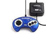
This connection is made throught a 25pin 1.25mm pitch FFC cable.
25pin connector on MCD1
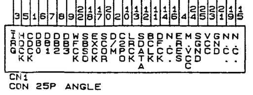
Mixing informations from the service manuals available online, we also know the purpose of each of the 25 pins :
X'Eye interface connection
Main board
On the main board, we could find
- 68000 (SUB CPU)
- Sega 515-5548 (Game Processor)
- LC 8951 (CD ROM processing)
- LC 7883 (CD DA processing)
While 68000 is MegaCD's CPU, its brain is the Sega 515-5548.
This ASIC drives every component of the MegaCD : memory, data, sound, CD...All of them send / receive command to/from the 515-5548.
Note: all data are digital data, EVEN FOR AUDIO
What is happening on the main board ?
- CPU sends a request to Game Processor
- Game Processor analyses this request to identify IC required (memory, sound, video, data ...)
- If it's a CD-related request, the Game Processor waits for the CD controller to be ready, reads its status and sends back the command to fulfill the request.
- Based on the command sent, CD controller will return CD info (subcode, status), stream audio to Game Processor (which will forward attenuated version to LC7883) or stream data to LC8951)
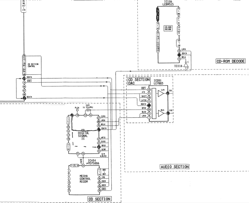
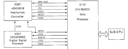
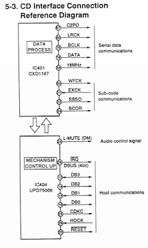
CD board
On the CD board side, we could find
- CXP5084 (4bit micro computer - Mechanism Controller "MiCom")
- CXP2500AQ (CD DSP)
- CXA1372AQ (CD Driver - RF Amplifier / Servo controller)
- CD drive
What is happening on the CD board ?
- When it's ready, MiCom sends status or answer of previous command to Game Processor
- MiCom receives a new command from Game Process
- MiCom translates this command for the CD DSP and/or CD Driver
- CD Driver sets up CD-drive
- CD-drive flows data to the CD Driver
- CD Driver checks/applies error correction on data
- CD Driver sends error-free data to CD DSP
- CD DSP informs MiCom if data is audio or not
- CD DSP informs MiCom of its status
- CD DSP sends serialized data LC8951 OR audio to Game Processor
- CD DSP identifiy if data is read for first frame of a sector or not
- CD DSP send subcodes and frame start indicator to Game Processor
- MiCom compute status/answer and .... loop
Based on the hardware, we could refine the CD workflow to
- status sent by MiCom
- commands received by MiCom
- audio/rom/subcode data handled by CD DSP
MCD2 CD interface connection
??Don't forget !ERES
To emulate the CD controller means to be able to handle
- timed communication with Game Processor
- process command and update status
- serialization of CD data to Game Processor or LC8951
- serialization of CD subcodes to Game Processor
- CD drive operations
Timed communication with Game Processor
Game Processor receives status and sends commands from/to MiCom.
The process is available on page 78 of MegaCD 1 manual and page 21 of XEye technical manual
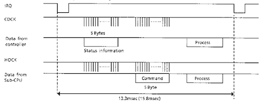
Within the communication frame, MiCom will
- latches an IRQ when ready
- sends 5bytes (10x 4bit nibbles) of status to Game Processor
- receives 5bytes (10x 4bit nibbles) of command from Game Processor
- process command (see next chapter)
TBCWhich commands should be proceeded within the time frame vs commands should be proceeded within several time frames/sectors ?
IRQ is latched by the MiCom, when ready, and reset after ?? usec.
An IRQ is latched every 1/75s (13.3ms) while data transfer is on progress , time for a full CD Track's sector,
and every 15.8ms if not. TBC
Game Process acknowledge the start of a new communication frame starting its HostClock (HOCK).
HOCK starts 8usec after IRQ latch.
??frequency unknown (4Khz?)
MiCom starts its MiComlock (CDCK) 33usec after HOCK start, acknowledging Host comm.
It sends its status nibbles in sync with CDCK.
??frequency unknown (4Khz?)
After the 10 nibbles of MiCom, Game Processor send its command nibbles in sync with HOCK.
??frequency unknown (4Khz?)
After the 10 nibbles of Game Process, HOCK and CDCK are stopped.
TBC
MiCom and Game Process handle their own received nibbles and launch related tasks.
Nibbles are 4 bits sent in parallel on the databus (D0-D4).
At ?? Hz, sending 20 nibbles take ?? ms.
It means MiCom and Game Process have at least ?? ms to process received command/status before next IRQ.
Warning:
It's the Game Processor who drives the communication with its clock.
IRQ latch is a "I'm ready" signal, not a "Be ready" signal.
and MiCom answers to Host clock (not reverse).
Process command and update status
MiCom "translates" the received command to the CD Driver, the CD DSP or the drive itself.
It could so update its status for next frame and optionnaly the D/M signal.
Data are not handled by the MiCom itself, but by the CD DSP
Commands
Commands were not documented because Sega prohibited developpers to direct access the MiCom (see page 33 of MegaCD Hardware manual)
Hopefully, Stef, Michel Gerritse and Eke did a really great job to discover commands / status through BIOS analysis and hardware testing, to improve MegaCD emulation.
Years later, the JVC XEyes technical manual was found which include commands but also errors code (but not status!).
The 9 commands values (TCx) are nibble so between 0x00 and 0x0F
TC0: command ID (see MiCom Commands))
TC1: 0
TC2: MSN of Minute (BCD)
TC3: LSN of Minute (BCD) => TC2-TC3 = MM
TC4: MSN of Second (BCD)
TC5: LSN of Second (BCD) => TC4-TC5 = SS
TC6: MSN of Frame (BCD)
TC7: LSN of Frame (BCD) => TC6-TC7 = FF
TC8: 0
TC9: checksum <= NOT(TC0-8) & 0xF
MiCom Commands
|
TC0 |
Name |
Parameters |
Notes |
| 0x00 |
NOP |
- |
|
| 0x01 |
STOP |
- |
Stop drive and lazer
current position is 00:00:00 |
| 0x02 |
REQUEST |
TC3 : request code
TC6-7: if TC3 = 5
|
status according request |
| 0x03 |
READ/PLAY |
TC1-TC9 : start position |
SEEK to start position THEN Play music / Read data
??seek time to be defined |
| 0x04 |
SEEK |
TC1-TC9 : start position |
Move to position and wait
??seek time to be defined |
| 0x05 |
unused |
|
|
| 0x06 |
PAUSE |
- |
|
| 0x07 |
RESUME |
- |
Resume playing after one of the previous command (0x01 to 0x06)
no SEEK needed |
| 0x08 |
SCAN-FF |
- |
Fast forward/td>
|
| 0x09 |
SCAN-FR |
- |
Fast rewind/td>
|
| 0x0A/0x0B |
TRACK ACCESS |
TC3: direction (forward/rewind)
TC4-7: seek length (*) |
Doc mismatch between 0xA and 0xB, to confirm |
| 0x0C |
CLOSE |
- |
Close tray and STOP
Only valid on MCD1 ? |
| 0x0D |
OPEN |
- |
STOP and Open tray
Only valid on MCD1 ? |
| 0x0E |
MISC |
???? |
WonderMega exclusive ? to confirm |
| 0x0F |
unused |
|
|
Request code
|
Code |
Description |
Parameters |
Status |
Notes |
| 0x00 |
get absolute time |
- |
absolute time on RS2-7 |
|
| 0x01 |
get present time |
- |
present time on RS2-7 |
|
| 0x02 |
get current track indedx |
- |
track index on RS2-3 (BCD), 1-based
defaut:0x0A0A (see Eke) |
|
| 0x03 |
get end time (TOC end) |
- |
total CD duration on RS2-7 |
|
| 0x04 |
get first and last track indexes |
- |
first track index on RS2-3 (BCD), so 1
last track index on RS4-5 (BCD)
frame is 00 |
|
| 0x05 |
track start time |
Track index in TC6-7 (BCD) |
starttime on RS2-7
track index on RS8 |
|
| 0x06 |
get last error code |
- |
last error code on RS2-3 |
see below |
| 0x0F |
host is not ready |
- |
update status like with 0x00 |
it won't process data send nor acknowledge IRQ ? |
While these commands are probably enough to handle most games, I won't be surprised to find more with
- Flux analysis
- Wonder libray analysis
- X eyes and WonderMega bios analysis (especially the 0xE command)
Status
The 9 status values (RSx) are nibble so between 0x00 and 0x0F
RS0: MSN of status (see Code Status)
RS1: LSN of status : 0 or, if command 0x2, TC3 back
RS2: MSN of Minute (BCD) or see command 0x2 (TC3 = 0x3) and 0x3
RS3: LSN of Minute (BCD) or see command 0x2 (TC3 = 0x3) and 0x3
RS4: MSN of Second (BCD) or see command 0x2 (TC3 = 0x3)
RS5: LSN of Second (BCD) or see command 0x2 (TC3 = 0x3)
RS6: MSN of Frame (BCD)
RS7: LSN of Frame (BCD)
RS8: 0 or see command 0x3 (TC3 = 0x5)
RS9: checksum <= NOT(RS0-8) & 0xF
??according Eke, RS8 (bit0 = mute status, bit1: pre-emphasis status, bit2: track type), ie Q Control bits ?
Status code
|
Code |
Name |
Description |
Notes |
| 0x00 |
STOP |
stopped |
|
| 0x01 |
PLAY |
Playing music or loading music |
|
| 0x02 |
SEEK |
Moving to requested time |
|
| 0x03 |
SCAN |
scan in progress |
|
| 0x04 |
PAUSE |
paused |
not stopped (0x00) |
| 0x05 |
OPEN |
tray opened |
there is no closing status |
| 0x06 |
SUM_E |
Error communication checksum |
RS8-9 / TC8-9 error |
| 0x07 |
COMMAND_E |
Missed the last command |
too busy to handle it ? request host to send it again ? |
| 0x08 |
ERROR |
send error code (see below) |
wait for the get last error command or not ? |
| 0x09 |
TOC |
Readind TOC |
|
| 0x0A |
TRK_MOVE |
moving to requested track |
|
| 0x0B |
DISC_E |
No disc |
|
| 0x0C |
END_DISC |
drive reach lead-out |
|
| 0x0D |
not used |
|
|
| 0x0E |
TRAY |
Manual action on tray |
|
| 0x0F |
TEST |
Test mode |
??? which test mode |
Error code
|
Code |
Name |
Description |
Notes |
| 0x00 |
NO-ERROR |
- |
|
| 0x03 |
E-FOCUS |
Focus down for more than 100msec |
will retry until ok or issue an error 0x08 |
| 0x04 |
E-TRK |
Returned to the normal state |
?? whatever it means !!! |
| 0x05 |
E-GFS1 |
No sync |
|
| 0x06 |
E-GFS2 |
No sync |
diff wih 0x05 ? |
| 0x07 |
E-ACCESS |
Timeout accessing CD |
|
| 0x08 |
E-FOCUS2 |
Unable to focus |
|
Serialization of CD data to Game Processor or LC8951
Whatever the data is (Audio or others), its flows on the SDATA line, serialized.
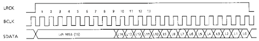
Thanks to l_oliveira, we know it uses the I2S protocol, with
- a bit clock (BLCK), so send each bit
- a frame clock (LRCK), to drive left (HIGH) then right (LOW) channel
- serial data (SDATA)
- + error flag (C2PO)
- + mute flag(D/M)
According I2S specification, BLCK is sample rate x number of channels x bits per channel.
Note: CXD2500AQ has a 48bits (24 bits per channel) precision.
So we need to send 16bit + two's complement 8 bits first
LRCLK is sample rate
SDATA will so send its bits at audio speed, even if it's data
C2 Parity Output will raise when CD DSP was unable to fix error
D/M will raise if data should not be forwarded to LC7883
So, in fine, we have
- BCLK = 2.1168MHz (16MHz/8)
- LRCK = 44.1 KHz
- SDATA = channel L then channel R
- C2PO = 1 if error (0 if not)
- D/M = 1 if data, 0 if audio
Serialization of CD subcodes to Game Processor
Subcodes are send throught dedicated pins
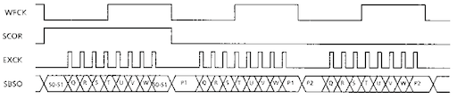
- frame clock (WFCK) : so 1/75/98 (98 channel frames per sector) -> 7.35KHz TBC
- block clock (SCOR) : raise when sync word are detected
- host clock (EXCK) : init by host (10us after WFCK fall) to receive bit, at 1MHz
- serial data (SBSO) : 8 bits per sector, 1bit x 8 subcode
SBSO updates its bit's value after EXCK raise, so it means 9 update for 8 bits.
The last bit is probably a false one (ie not read by Game Processor).
On every datasheet I read, they ask it to the same than first bit.
CD DSP probably roll the subcode byte, not shift it.
SCOR is set when SYNC word is detected.
So basically, on 2nd frame when CD DSP decoded S0 and S1 bytes.
SCOR is NOT a frame start indicator since first frame (with SO byte) doesnt rise it.
If you want to know more, the "Description of the prior art" of this patent is propably the easiest document to read I found
CD drive operations
a CD drive is able to
- open/close tray or door, if available
- detect valid CD
- access to lead-in (TOC) and lead-out
- jump/seek to a specific frame
- transmit/read a frame to DSP
- stop/resume
Nothing new here.
Analysis of documents is not enough to emulate a system, you need clear details about timing and undocumented informations.
To cover this, you need the real hardware and an oscilloscope.
These is some of the signals I need to capture captured to confirm or fix informations on the flow
Timed communication
- IRQ duration
- IRQ frequency on reading data vs on stop
- HOCK frequency
- CDCK frequency
- Nibbles transmit time vs process time
- how many time before IRQ after a reset ?
Command
- First comm' frame content
- one comm' frame vs multi comm' frame command
- seek time
- RS8 value
Data
- data and D/M on gap and lead-in
- what happen when not reading
Subcode
- WFCK frequency
- EXCK frequency
- delay between WFCK fall and EXCK start
- SCOR on 2nd frame ?
- 9th bit value
WIP
(unfortunately, HardwareMan's captures were lost when the image provider he used ended it services)

source
CD virtual drive
SD Card reader, SDIO 4Bit-mode with a way to
- select a file (close tray with disc)
- eject a file (open tray)
- select no file (close tray with no disc)
- answer to OPEN/CLOSE commands from MiCom
- access to sector data frame per frame
- (read/recreate) subcodes
- switch between original drive and virtual drive (non destructive mod for MCD1)
CD image file should support subcode data, for CD+G and TOC info (not error)
WIP
Disclaimer
This page is always in WIP mode.
A lot of informations are still missing or incomplete, so use them as a basis not as official documentation !
Thanks
This page wouldn't exist without the help of
- HardwareMan (data capture and analysis)
- Stef (MiCom reverse engineering)
- Eke (more MiCom reverse engineering)
- l_oliveira (I2S protocol)
- Nemesis (LC8951 doc)
- omp (service manual funds)
- others members involved in the related post
thanks guys, it's what make me so proud to host SpritesMind
|