Help with setting FM patch values
Posted: Sun Jan 26, 2014 5:18 pm
Hi, I'm writing a music player for the Mega Drive, but I'm having some unusual problems that I don't understand.
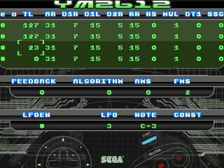
I've written a simple FM patch editor which exposes all the values for the operator lines so I can make new instruments and see what they sound like. (zip) A and B increase or decrease the values. C does a note on. Start does a note off. (screenshot)
My problem is that the values for the operators don't seem to be matching up with what I expect the note to sound like.
Read from top to bottom on my grid, the topmost line is operator 1 (the self-feedback line) and the bottommost line is operator 4, corresponding to M1 C1 M2 and C2 on the normal FM algorithm diagrams. The default values should give a note that's clear and loud and eventually decays.
If I enable just operator 4 by itself and trigger note on, I get the sine tone which is expected. If I enable lines 3 and 4 together, I don't get the effect I expect. With the values in this screenshot, I'm expecting to get the unmodulated sine tone I would get if only line 4 were enabled (because the TL for line 3 is 127 so it should be silent), but it appears that when line 3 is enabled, it's using all the values from line 2. It seems that the values for lines 2 and 3 are swapped perhaps?
I'm confident that my code is swizzling together the correct values, as the YM debugger in Regen is showing that the FM registers all contain what I'm expecting. (EN is operator line enable = Key at the bottom. AE = Amp Mode?, TL = Total Level, AR = Attack Rate, D1R = First Decay, D1L = Sub Level, D2R = Second Decay, RR = Release Rate, RS = Rate Scaling, MUL = Multiple, DT1 = Detune), but I might not be putting them into the correct registers.
Here is how I'm assigning the values. Could somebody tell me if I've mixed something up along the way?
My code assembles all the necessary FM register values and loads them into [$30...$8C] for channel 0:
The first operator (M1) line's values go into $30, $40, $50...
The second operator (C1) line's values into $34, $44, $54...
The third operator (M2) line's values into $38, $48, $58...
The fourth operator (C2) line's values into $3C, $4C, $5C...
The EN column refers to the operator bitmask used when sending a 'note on' in FM register $28, with the lines in the bitmask arranged as %4321xccc. (ccc is channel and is always zero in this program)
Cheers.