http://www.fileden.com/files/2008/4/21/1876835/MD11.jpg
http://www.fileden.com/files/2008/4/21/1876835/MD12.jpg
My MD1... socketed YM2612 and 2 jumpers for region are all what's done...
New Documentation: An authoritative reference on the YM2612
Moderator: BigEvilCorporation
-
TmEE co.(TM)
- Very interested
- Posts: 2456
- Joined: Tue Dec 05, 2006 1:37 pm
- Location: Estonia, Rapla City
- Contact:
Mida sa loed ? Nagunii aru ei saa 
http://www.tmeeco.eu
Files of all broken links and images of mine are found here : http://www.tmeeco.eu/FileDen
http://www.tmeeco.eu
Files of all broken links and images of mine are found here : http://www.tmeeco.eu/FileDen
-
HardWareMan
- Very interested
- Posts: 757
- Joined: Sat Dec 15, 2007 7:49 am
LED wire hinders see wich "VA" your board. Is it "VA4" as mine?TmEE co.(TM) wrote:http://www.fileden.com/files/2008/4/21/1876835/MD11.jpg
http://www.fileden.com/files/2008/4/21/1876835/MD12.jpg
My MD1... socketed YM2612 and 2 jumpers for region are all what's done...
-
TmEE co.(TM)
- Very interested
- Posts: 2456
- Joined: Tue Dec 05, 2006 1:37 pm
- Location: Estonia, Rapla City
- Contact:
Yes, VA4, just like yours.
Mida sa loed ? Nagunii aru ei saa
http://www.tmeeco.eu
Files of all broken links and images of mine are found here : http://www.tmeeco.eu/FileDen
http://www.tmeeco.eu
Files of all broken links and images of mine are found here : http://www.tmeeco.eu/FileDen
-
Chilly Willy
- Very interested
- Posts: 2996
- Joined: Fri Aug 17, 2007 9:33 pm
If I remember the discussion right, there are six channels with four operators each. Instead of summing all twenty four operators and outputting the result as one value, instead the four operators for each channel are summed and output as one value during one of eight time slots - one time slot for each channel plus one slot for DAC and one for ? didn't catch the last one. Putting out six distinct analog values at different times is NOT going to sound the same as adding six values together and presenting it once.Snake wrote:That doesn't even make sense.Nemesis wrote:The accumulator combines the output from operators, it does not combine the output from channels.
For gods sake. No.Chilly Willy wrote:If I remember the discussion right, there are six channels with four operators each. Instead of summing all twenty four operators and outputting the result as one value, instead the four operators for each channel are summed and output as one value during one of eight time slots - one time slot for each channel plus one slot for DAC and one for ? didn't catch the last one. Putting out six distinct analog values at different times is NOT going to sound the same as adding six values together and presenting it once.Snake wrote:That doesn't even make sense.Nemesis wrote:The accumulator combines the output from operators, it does not combine the output from channels.
Operators have inputs. They take care of this stuff. If they didn't, there would BE no 'FM'. It. Does. Not. Make. Sense.
The 6 outputs go to the accumulator and then to the DAC.
Other chips in the YM range don't have an internal DAC. The data that goes out to the DAC has been intercepted and interpreted by others many times.
This is already well documented and I can't believe I'm even wasting my time discussing it. In fact, I'm going to stop now.
Snake wrote:That doesn't even make sense.Nemesis wrote:The accumulator combines the output from operators, it does not combine the output from channels.
Algorithms 0, 1, 2, and 3 have 1 carrier. Algorithm 4 has 2. Algorithms 5 and 6 have 3. Algorithm 7 has 4. The accumulator sums the output from all these carriers within a channel, and presents each channel as a single output to the DAC. It also handles the DAC signal for channel 6, and the left/right channel outputs.
The accumulator has the job of taking a possible 24 carrier outputs from the operator unit (when each channel is running in algorithm 7), and presenting it to the DAC as 12 distinct output streams, 6 going to the left speaker, and 6 going to the right speaker. Both speaker outputs use multiplexing to interleave the 6 operator output streams directed at that speaker.
Sure, the accumulator could have summed each channel and presented it to the DAC as two combined output streams, one to the left speaker, and one to the right speaker. Why didn't they? Maybe they figured they get a better effective output bitrate this way. The audible output sounds pretty much the same, and they didn't have to lose precision by combining the 6 channels into 1 while the output was still in digital form, which would have cut the effective bitrate of each channel. Maybe this was just easier. Hell, I don't know. All I can tell you is, it's obvious the output stream is multiplexed when you hook up any equipment which can sample fast enough to notice it. Anything that's sampling at around 96KHz or less is just going to be combining all those outputs into one during the capture process, so it'll just look like a continuous, combined signal. Your ears are doing the same. My oscilloscope isn't lying though. It's digital, I can post some screenshots if you'd like.
Ok, one last time.
The MAME team discovered, and documented, a very long time ago, that a YM2610 divides the output by two after adding all channels together, because the addition of the extra ADPCM channels would have caused clipping otherwise. They did this by examining the output to the DAC, not by just sampling the output.
This isn't the job of the accumulator. Do you have any idea what speed the DAC would have to operate at if if was receiving 12 seperate streams? Remember this thing is SERIAL. Doing things this way makes zero sense at all when an adder is one of the simplest things to implement.Nemesis wrote:The accumulator has the job of taking a possible 24 carrier outputs from the operator unit (when each channel is running in algorithm 7), and presenting it to the DAC as 12 distinct output streams, 6 going to the left speaker, and 6 going to the right speaker.
Why, because you can see gaps between samples? Yeah, that's how a DAC works. You're looking at multiple samples, not multiple channels.Nemesis wrote:All I can tell you is, it's obvious the output stream is multiplexed when you hook up any equipment which can sample fast enough to notice it.
The MAME team discovered, and documented, a very long time ago, that a YM2610 divides the output by two after adding all channels together, because the addition of the extra ADPCM channels would have caused clipping otherwise. They did this by examining the output to the DAC, not by just sampling the output.
*facepalm*
http://nemesis.hacking-cult.org/MegaDri ... lexing.asm
http://nemesis.hacking-cult.org/MegaDri ... lexing.bin
Do the test yourself. I'm not going to argue this point any longer.
http://nemesis.hacking-cult.org/MegaDri ... lexing.asm
http://nemesis.hacking-cult.org/MegaDri ... lexing.bin
Do the test yourself. I'm not going to argue this point any longer.
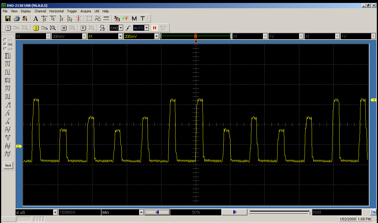
Ehh, for posterity, I'm going to elaborate anyway. The test I just posted uses a single operator from each channel. The phase generator is frozen, with the phase generator outputting a maximum positive value each cycle. The envelope generator for the selected operator in each channel is locked in an infinite decay phase, at an effective internal attenuation value of 0. A different TL value is used for the selected operator in each channel. The overall effect of this is that each channel has a constant output. The attenuation level that each channel sits at is controlled by TL.
The screenshot I posted shows the output from the YM2612, sampled directly from the chip with an oscilloscope. If all the channels were summed, and the gaps were gaps between successive samples, every sample would be the same value. As you can see, the levels between each successive sample differ, with each sample clearly representing a different channel with a different attenuation value, as set by TL. Here's another screenshot I've just taken:
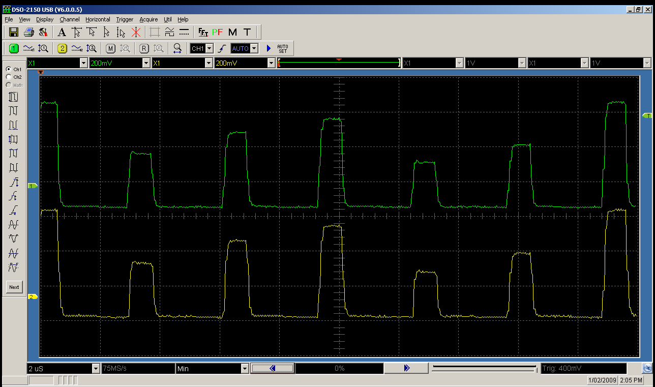
This one shows both the left and right channels, and this time, I've used unique values for TL in each channel, moving from 0x0 to 0xA with a step of 2 from channel 1 to channel 6. Channel 1 is the one mostly visible on the lefthand side. You can see how the channels are actually output out of order. The apparent output order is 1,5,3,2,6,4. Also, according to this, the left and right output streams are actually output at the same time, which I find a little surprising.
In terms of the frequency the DAC would have to run at, if we assume the YM2612 does use an embedded YM3016, if it was only doing a single channel, the YM3016 would need to be running at a minimum clock rate of around 5.07MHz, which is above its reported maximum clock input of 5MHz. This does suggest the YM2612 may be using a different DAC. It's also possible it uses two DAC's, one for the left channel, and one for the right channel, and controls them both in parallel. At any rate, it does appear that the YM2612 does its DAC conversion quite differently than the known OPN chips that have an external DAC, like the YM2608.
The screenshot I posted shows the output from the YM2612, sampled directly from the chip with an oscilloscope. If all the channels were summed, and the gaps were gaps between successive samples, every sample would be the same value. As you can see, the levels between each successive sample differ, with each sample clearly representing a different channel with a different attenuation value, as set by TL. Here's another screenshot I've just taken:
This one shows both the left and right channels, and this time, I've used unique values for TL in each channel, moving from 0x0 to 0xA with a step of 2 from channel 1 to channel 6. Channel 1 is the one mostly visible on the lefthand side. You can see how the channels are actually output out of order. The apparent output order is 1,5,3,2,6,4. Also, according to this, the left and right output streams are actually output at the same time, which I find a little surprising.
In terms of the frequency the DAC would have to run at, if we assume the YM2612 does use an embedded YM3016, if it was only doing a single channel, the YM3016 would need to be running at a minimum clock rate of around 5.07MHz, which is above its reported maximum clock input of 5MHz. This does suggest the YM2612 may be using a different DAC. It's also possible it uses two DAC's, one for the left channel, and one for the right channel, and controls them both in parallel. At any rate, it does appear that the YM2612 does its DAC conversion quite differently than the known OPN chips that have an external DAC, like the YM2608.
-
HardWareMan
- Very interested
- Posts: 757
- Joined: Sat Dec 15, 2007 7:49 am
Whoa... Channel order is not "123456"? As for multiplexing output, I had already say: 6 timeslots per one channel (left and right). That's is why DAC function replace one of channel (number 6). Nemesis, please make measurement of time (frequency) between start of every timeslot and time of width of one timeslot.
ARGH pictures too big, lots of scrolling...
Ok, your pictures are interesting.
I did do similar tests many years ago, using equipment owned by a guy I worked with. I didn't see the same results. Maybe his equipment wasn't good enough. Maybe this was changed in later chips. I don't know now. Still...
The operators/channels take care of themselves. The function of the accumulator is, absolutely, to sum the channels. If it's not doing that it actually suggests they REMOVED the accumulator. They did exactly this (and it's documented) in some simpler chips, but the YM2612 sounds much cleaner.
In any case, I still say this isn't the reason for the distortion we are hearing. Just as well, because any way you try to downsample that it's just going to sound pretty much the same as if they were mixed. Only playing it at the same frequency is going to sound the same.
Ok, your pictures are interesting.
I did do similar tests many years ago, using equipment owned by a guy I worked with. I didn't see the same results. Maybe his equipment wasn't good enough. Maybe this was changed in later chips. I don't know now. Still...
The operators/channels take care of themselves. The function of the accumulator is, absolutely, to sum the channels. If it's not doing that it actually suggests they REMOVED the accumulator. They did exactly this (and it's documented) in some simpler chips, but the YM2612 sounds much cleaner.
They will be, it's a stereo DAC.Nemesis wrote:the left and right output streams are actually output at the same time, which I find a little surprising.
I make it 5.11MHz (and twice that if, as you originally suggested, it did 12 passes) - but it's probably more than that because the chip requires some time to do the actual conversion and settle.Nemesis wrote:In terms of the frequency the DAC would have to run at, if we assume the YM2612 does use an embedded YM3016, if it was only doing a single channel, the YM3016 would need to be running at a minimum clock rate of around 5.07MHz
Yes, I mentioned this before. I knew it was a different DAC, but it seems very odd that they would put a faster DAC in there instead of an accumulator.Nemesis wrote:This does suggest the YM2612 may be using a different DAC.
In any case, I still say this isn't the reason for the distortion we are hearing. Just as well, because any way you try to downsample that it's just going to sound pretty much the same as if they were mixed. Only playing it at the same frequency is going to sound the same.
I can go one better than that:Whoa... Channel order is not "123456"? As for multiplexing output, I had already say: 6 timeslots per one channel (left and right). That's is why DAC function replace one of channel (number 6). Nemesis, please make measurement of time (frequency) between start of every timeslot and time of width of one timeslot.
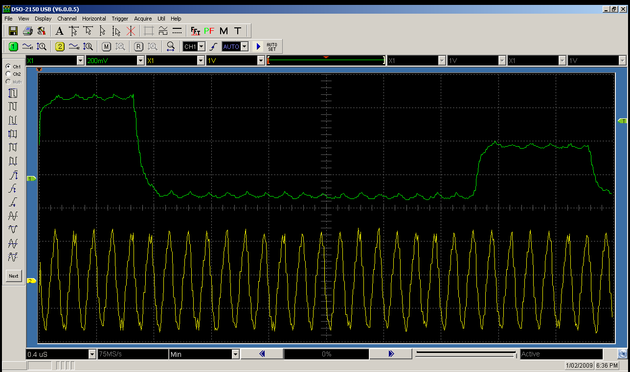
This is the analog output from the YM2612 next to the master clock (7.61MHz or there abouts). As you can see, there are 24 master clock cycles between each timeslot. The silence gap is most likely at the start of the timeslot, and represents the period in which the accumulator is sending the serial data stream to the DAC. Looking at the bus communication diagram in the YM3016 datasheet, with 16 bits of data to stream, that's 16 cycles used for the data transfer, plus an extra 2 cycles, one before the start of the stream, and one after the end of the stream, for the data latch input, plus an extra 1 cycle before the final latch input, where the SMP1/2 lines are negated. That gives 19 cycles for the serial communication, which is the observed gap of silence between each output, leaving only 5 cycles for the output to remain asserted across a full clock cycle, which is exactly what we see on the image above.
Tying this back into the clock rates used in the YM2612, the DAC has one timeslot per channel, or 7610000/6/4=317083, where 6 is the fm prescaler, and 4 is the number of operators per channel. The actual DAC runs at the full input clock rate. Oh, and based on the datasheet for the YM3016, it looks like both channels can be programmed at once on that device (IE, the DAC can latch a single output stream and send it to both channels), and seeing as the communication between the accumulator and the DAC seems to match the communication pattern of the YM3016, it seems the embedded DAC is most likely a YM3016 derivitive. Since this embedded DAC is obviously running at 7.61MHz however, it must support a higher clock input. The YM3016 was only rated for a max of 6MHz (not 5MHz like I said earlier, that was the YM3015. Perhaps this would make the DAC model a YM3018?).
EDIT: Some googling seems to confirm that the YM3018 does exist, but there seems to be absolutely no information on it.
Last edited by Nemesis on Sun Feb 01, 2009 7:51 am, edited 1 time in total.
Well, as I mentioned before, I read somewhere (fucking wish I could remember where) that it's only 9 bit. That would seem to make more sense now, wouldn't it? No point in putting a full 16-bit capable DAC in there if it's not going to get used.Nemesis wrote:it seems the embedded DAC is most likely a YM3016 derivitive.
That channel order is fucking strange, though.
Last edited by Snake on Sun Feb 01, 2009 7:59 am, edited 1 time in total.
-
HardWareMan
- Very interested
- Posts: 757
- Joined: Sat Dec 15, 2007 7:49 am