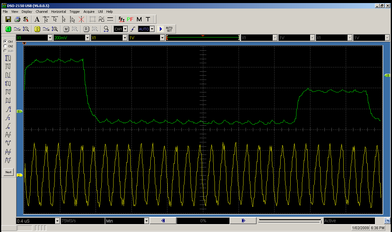
The screenshot I posted shows the output from the YM2612, sampled directly from the chip with an oscilloscope. If all the channels were summed, and the gaps were gaps between successive samples, every sample would be the same value. As you can see, the levels between each successive sample differ, with each sample clearly representing a different channel with a different attenuation value, as set by TL. Here's another screenshot I've just taken:
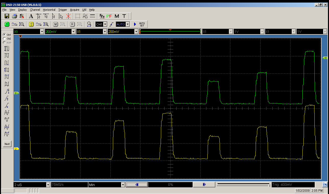
This one shows both the left and right channels, and this time, I've used unique values for TL in each channel, moving from 0x0 to 0xA with a step of 2 from channel 1 to channel 6. Channel 1 is the one mostly visible on the lefthand side. You can see how the channels are actually output out of order. The apparent output order is 1,5,3,2,6,4. Also, according to this, the left and right output streams are actually output at the same time, which I find a little surprising.
In terms of the frequency the DAC would have to run at, if we assume the YM2612 does use an embedded YM3016, if it was only doing a single channel, the YM3016 would need to be running at a minimum clock rate of around 5.07MHz, which is above its reported maximum clock input of 5MHz. This does suggest the YM2612 may be using a different DAC. It's also possible it uses two DAC's, one for the left channel, and one for the right channel, and controls them both in parallel. At any rate, it does appear that the YM2612 does its DAC conversion quite differently than the known OPN chips that have an external DAC, like the YM2608.