Synlor- 27th February 2005
The Genesis
controller is quite simple because it just multiplexes 2 buttons
onto 1 line, making decoding fairly simple.
History: V. 0.1 First document
Equipment: Disclaimer: I am not responsible of what you do with these
directions, nor responsible for what it can do to your dreamcast,
vmu, or anything else that is in your possession.
How it works: Now you may be wondering on how that could work, and the answer
is quite easy. There is one pin on that chip that is known as the
select pin. This pin determines which of the 2 lines should be
outputted on the final line by either being high or low. For
example, the A and B button are sent to the console by 1 wire. When
this select line is at +5 volts (high) the status of the B button is
outputed. When it is low (ground) the status of the A button is sent
to the console. The genesis acts as active low, so in the previous
example it would work like this. With the select line high, and the
B button not being pressed, the output would be +5 volts. If the B
button is pressed than the output would be low (ground). Now when
the select line is low, and the A button is pressed, the output is
once again high. And once again when the button is pressed it is
low. We can decode the controller by raising and lowering the select
line and reading each output.
Here is a visual example of this: The following table is which buttons go with which pin on the
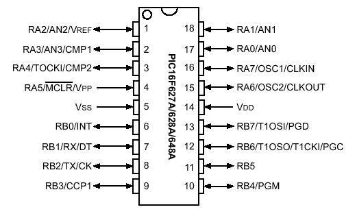
Genesis connector, and how they react with the select line: Program: Download: Interfacing: This table shows which pins on the PIC represent each button
(active low):
The Genesis controller needs 9 wires to
function, 2 being +5 volts and ground. The other 7 contain the
information on which button is pressed. Inside the Genesis is a quad
multiplexer chip, a 74HC157. This chip takes in information from 2
lines (high or low) and puts it togethor in one single line.
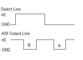
The letter B
represents when the B button is pressed, and letter A represents
when the A button is pressed.
Pin #
Select High
Select Low
1
Up
Up
2
Down
Down
3
Left
Ground (low)
4
Right
Ground (low)
6
B
A
9
C
Start
The program simply raises the select line,
then determines which button is pressed by reading the output lines
of the controller. Once it knows which buttons are pressed, it will
set the corresponding pin low (active low). The same is done with
select low, and then it loops back to the beginning and runs through
the whole process again.
Source
Code
Hex
file for a 16F628A
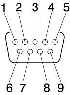
The above 9
pin connector is when you are looking console's plug. The following
table shows which pin from the genesis controller connects to the
correct pin on the PIC MCU:
Genesis Pin #
PIC Pin
1
A6
2
A7
3
A1
4
A2
5
VCC
6
A3
7
A0
8
VDD
9
A4
Finally the power needs to be hooked up
to the PIC, +5 volts to VCC, and ground to VDD.
Button
PIC Pin
Left
B0
Right
B1
Up
B2
Down
B3
A
B4
B
B5
C
B6
Start
B7