Building a Jamma test rig / Supergun
Author:
©
1998 – 2005 Chad Gray
Rescued From The Web Archives by: magic
lord of RLLMUK forum
Converted to Word Format by: roberthazelby
of RLLMUK forum
www.rllmukforum.com
Introduction
- What is a SuperGun?
For those browsing in from Military Sites doing checks on what people are up to: Don't Panic! This hasn't got anything to do with weapons :-)
Arcade games are designed to be played standing up in front
of a machine which you can safely give a good kick if things don't go your way
:-) However,
I don't know where the name came from, but a "Supergun" (a.k.a. "Jamma box" or "Jamma Test Rig") is a device which allows you to play arcade PCB's without having to use an arcade cabinet. It uses your TV or other suitable monitor as a display and you plug joysticks or other controllers into it. Sound familiar? Bit like a console really, isn't it? There are other benefits besides the space saved by not needing a cabinet, namely it's use as a test rig. If you're wiring up a Jamma adapter or attempting to repair a board, a supergun allows free access to the PCB under scrutiny whilst it is powered up, and you can see the screen whilst working on the board - try that when you're delving in the back of a cabinet :-)
There are, however, a few drawbacks. Firstly, you are restricted to using horizontally orientated games only. This is because it is not wise to turn your telly onto it's side whilst playing :-) I suppose if you were using a small monitor of some description you may be able to rotate it however you wish. Secondly, televisions offer poor picture geometry correction controls. By this I mean the ability to resize and move the picture both horizontally and vertically. Not all games use the same resolutions and you may find that some work within a "window" on your screen whilst others are extended outside the viewable area. Again, use of a monitor may offer more control here. Also, some games require the V-sync to be set just so or the picture will roll. This can be altered on an arcade monitor but not on a TV.
But anyway, all in all it's a useful bit of kit to have just for the test rig aspect.
The device I built is designed to be fairly modular in construction - you may chose the type of controllers you wish to use and the type of display you have. Obviously I can't cover all the possibilities here but will cover some and you should be able to adapt the rest to suit your own needs.
What you will need
Here is a rough list of parts required to build the SuperGun. Remember that because this is a modular design some parts required will depend on which options *you* choose. For example, you will have to get a connector to fit *your* chosen display, and connectors to suit *your* choice of controllers. Whichever type of case you use is also entirely up to yourself.
Part |
Qty |
PC power supply or arcade power supply |
1 |
56-way Jamma edge connector |
1 |
Wire - I used 24/0.2 for the power lines and 16/0.2 for the rest |
10m lengths in at least 8 different colours is recommended |
PCB mounting 20mm fuseholder |
2 |
10A 20mm fuse |
1 |
2A 20mm fuse |
1 |
Stripboard |
25 holes by 15 strips |
Loudspeaker - 4" 8 ohm or similar |
1 (or 2 for stereo option - see text) |
Heat shrink sleeving |
1m |
6 way PCB mounting molex connector |
1 (for video connection) |
6 way molex connector header |
1 (for video connection) |
6 core cable |
1-2m (to video display) |
connector for your chosen video display - see text |
1 |
small push buttons (for coin insert etc) |
1-5 (see text) |
connectors for your chosen joysticks - see text |
2 |
Suitable box to house it in - see text |
1 |
Should you wish to use Megadrive joysticks there is a list of required parts for that option in that section of the document.
For
Identifying the connections
Refresh yourself with the Jamma pinout (you're advised to
print this out if you want to undertake this project as I refer to the pin
names as listed below. We can break the connections required by the Jamma
connector into 3 groups:
Solder Side |
Parts Side
________________________________|___________________________________
GND | A | 1
| GND
----------------------------|---|---|-------------------------------
GND | B | 2
| GND
----------------------------|---|---|-------------------------------
+5v | C | 3
| +5v
----------------------------|---|---|-------------------------------
+5v | D | 4
| +5v
----------------------------|---|---|-------------------------------
-5v | E | 5
| -5v
----------------------------|---|---|-------------------------------
+12v | F | 6 |
+12v
----------------------------|---|---|-------------------------------
- KEY
- | H | 7 |
- KEY -
----------------------------|---|---|-------------------------------
Coin Counter # 2
| J | 8 |
Coin Counter # 1
----------------------------|---|---|-------------------------------
Lock Out Coil # 2
| K | 9 |
Lock Out Coil # 1
----------------------------|---|---|-------------------------------
Speaker (-) | L | 10|
Speaker (+)
----------------------------|---|---|-------------------------------
| M | 11|
----------------------------|---|---|-------------------------------
Video Green
| N | 12|
Video Red
----------------------------|---|---|-------------------------------
Video Sync
| P | 13|
Video Blue
----------------------------|---|---|-------------------------------
Service Switch | R | 14|
Video GND
----------------------------|---|---|-------------------------------
Tilt Switch | S | 15|
Test Switch
----------------------------|---|---|-------------------------------
Coin Switch # 2
| T |
16| Coin Switch # 1
----------------------------|---|---|-------------------------------
2P Start
| U | 17|
1P Start
----------------------------|---|---|-------------------------------
2P Up
| V |
18| 1P Up
----------------------------|---|---|-------------------------------
2P Down
| W | 19|
1P Down
----------------------------|---|---|-------------------------------
2P Left
| X | 20|
1P Left
----------------------------|---|---|-------------------------------
2P Right
| Y | 21|
1P Right
----------------------------|---|---|-------------------------------
2P Button 1
| Z | 22|
1P Button 1
----------------------------|---|---|-------------------------------
2P Button 2
| a | 23|
1P Button 2
----------------------------|---|---|-------------------------------
2P Button 3
| b | 24|
1P Button 3
----------------------------|---|---|-------------------------------
| c | 25|
----------------------------|---|---|-------------------------------
| d | 26|
----------------------------|---|---|-------------------------------
GND | e |
27|
GND
----------------------------|---|---|-------------------------------
GND | f |
28|
GND
--------------------------------------------------------------------
Power connections (marked
above in red):
Jamma requires -5v, 0v (GND), +5v and +12v. All of these are supplied by a
standard PC power supply.
Inputs (marked above in green):
These are the joystick and fire button inputs from the control panel, the coin
inputs and the start buttons.
Outputs (marked above in blue):
These consist of the output to the monitor (Red, Green, Blue and video sync)
and the speaker outputs.
We'll ignore the coin lockouts and counters, and we'll tackle each of these
three sections individually.
Keying the Jamma connector
This is a very important step which will take you all of 5 minutes but will protect your boards from the possible damage which can be caused by plugging in the Jamma connector the wrong way up or offset.
Here's a picture of the Jamma connector as purchased:
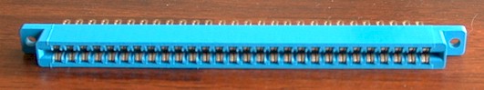
With the connector in this position, viewed from the front
and not the solderside, the bottom left pin is 1, the bottom right pin is 28.
The bottom side of the connector will connect with the component side of the
board.
The top left pin is pin A, the top right pin is pin f. This side of the
connector will make contact with the solderside of the board.
You'll have noticed from the Jamma pinout that position 7/H is marked as "Key", and that on a Jamma PCB there is a slot at this position. This is to polarise the connector, so that it is only possible to connect it the right way up and also that it has to be lined up correctly and not too far to one side or the other.
You need to remove the metal pins from the connector at the 7th position on both the top and bottom sides. I used a pair of long nosed pliers to grip the solder side of the metal contact and push it into the connector (that's towards you when viewed as in the picture above) You should find that they come out without too much difficulty.
Having removed the pins, you need to insert a small piece of plastic or similar into the gap to act as the key. I used a small section of plastic from a blanking plate normally used to cover a 5 1/4" drive bay on a PC. Snip it down to the approximate size using a hacksaw or side cutters and then trim it carefully until it fits tightly into the gap where the pins were.
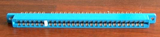
Use superglue or similar to ensure that it won't fall out! Now you're ready to start connecting things up.
Powering The Supergun From a PC Power Supply
For best results, you should really use an arcade power supply, it's what they were designed for after all.
I chose to use a PC power supply unit (PSU) for my test rig, because
- They're readily available
- They're reliable and fairly cheap
- They offer all the voltages we need
You should be able to pick up a new PC PSU for about £10. You don't need of of the newer style ATX PSUs with all the fancy power management systems, just an ordinary bog-standard AT PSU. Better still, if you have a dead PC or old PC case laying about you should be able to use the power supply from that.
PC power supplies provide the following voltages
Voltage |
Usual Wire Colour |
0v |
Black |
+5v |
Red |
+12v |
Yellow |
-5v |
White |
-12v |
Blue |
Note the usual wire colour may differ on *your* power supply - even if it doesn't you are advised to check the voltages with a multimeter. We don't need the -12v but the rest are required by the Jamma system.
+5v, 0v and 12v will be available on any of the connectors which you would normally plug into a disk drive or CD-Rom. -5v is only available on one of the connectors that plugs into the motherboard
PC PSUs are capable of delivering +5v and +12v at much higher currents than arcade PCBs generally require, typically they can deliver +5v at 20A (we only need about 10A) and +12v at 8A (we only need about 2A) so we'll use a couple of fuses to limit the amount of current we can draw off. This will help protect the PCB should it malfunction.
We'll use a 10A fuse in the +5v line and a 2A fuse in the +12v line.
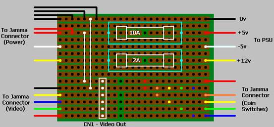
I used a small piece of stripboard to serve as an easy connection point for tapping off the power to the Jamma connector. We will only use one wire for each of the required voltages from the power supply but we need more than one going to the Jamma connector. A piece of stripboard makes this easy as we can use the strips as power rails. We can also house the fuses on this board.
To make things easy for yourself, you should use different colours of wire for each voltage. Ideally you should use the same colours as conventionally used in PCs (0v=black, +5v=red, -5v=white, +12v=yellow). This is not absolutely necessary but it makes your work easier to check and you'll be less likely to make a mistake.
Powering The
Supergun From a PC Power Supply (Continued)
I began by connecting up the power wires to the Jamma connector. I used wires
about 40cm long.
There are 8 ground connections to be made to the Jamma connector. To save on wiring I used 4 wires, threading each one through two pins on the Jamma connector, one for the solder side and one for the component side. So that's one wire for pins 1/A, one for 2/B, one for 27/e and one for 28/f. You should find that if you push the pins together first you can do this quite easily.
Similarly for +5v, there are 4 pins requiring +5v on the Jamma connector but again we can use two wires and thread each wire through two pins. One wire for 3/C and one for 4/D.
-5v goes to two pins on the Jamma connector, 5 and E, again we can use one wire for both of these.
+12v goes to pins 6 and F, which again are back to back to we can thread one wire through each of them.
You should now have something that looks a bit like this:

Once you've connected up these wires you should cover the pins where you have soldered with heat-shrink sleeving. This will serve to insulate the pins and prevent shorts etc. Don't forget that the Jamma connector and the PCB it's connected to are exposed when the SuperGun is running, unlike a cabinet!
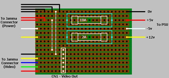
You should now bundle all the power wires together with cable ties at regular intervals. Now for that bit of stripboard I mentioned earlier. I used a piece 25 holes by 15 strips laid out as follows:
Powering The
Supergun From a PC Power Supply (Continued)
This is viewed from the
component side.
The copper strips are on the
underside of the board but are shown here for clarity.
The wires on the left of the board are those that go to the Jamma Connector, those on the right go to the power supply unit. I soldered the wires from the PSU directly to the stripboard, but you may want to use a connector of some sort so that the PSU could be easily removed for servicing etc. Make sure you cut the copper strip in the +5v and +12v rails somewhere under the fuse so that the power must travel through the fuses! You can then solder the fuseholders directly onto the stripboard as shown above.
We'll use the remaining space on the board for the video signals.
Audio Connections
This is dead easy - there's only two wires to connect to the Jamma
connector:
Signal |
JAMMA Location |
Speaker + |
10 |
Speaker - |
L |
Connect a wire to each of these pins on the Jamma connector. This time, make them longer than those used for the power connections so we have a bit more flexibility as to where we position our speakers.
Just connect the speaker terminals to these two wires and that's it done.
You may wonder why we use a speaker in the Supergun instead of outputting sound to a hi-fi or TV. Well, TV's and HiFi's require audio at line level, and the audio output from Jamma PCBs is already amplified. Therefore, there is a risk of damaging your audio equipment if it is connected to an already amplified signal. To prevent this risk I think it is safest not provide outputs to the audio signal.
Some PCBs may be capable of providing stereo sound, where standard Jamma only offers mono. Usually there will be an extra connector on the PCB for this. You may wish to provide a cable alongside the Jamma connector with a suitable plug on it which is connected to a pair of speakers to offer this facility. You could wire up a toggle switch so you can easily select either standard mono sound or stereo sound. The actual connector required to attach to the PCB will probably vary from game to game, but you could easily build an adapter to convert from whatever connector you use to that which the PCB expects.
Connecting up the video signals
There are five connections which make up the
video signals:
Signal |
JAMMA Location |
Suggested Wire Colour |
Red |
12 |
Red |
Green |
N |
Green |
Blue |
13 |
Blue |
Video Sync |
P |
Yellow |
Video Ground |
14 |
Black |
Connect a wire to each of these pins on the Jamma connector. The wires should be the same length as those you used for the power connections as we're going to solder them to the same piece of stripboard. Again, you should use heat-shrink sleeving to cover the pins on the Jamma connector once you have soldered your wire on to them. Once you have done this, tie this group of wires together at regular intervals with cable ties.
Now for that piece of stripboard again. There are only 5 signals required for the video, but +5v would be a useful addition to include in our video connector as it can be used to tie blanking signals high in a Scart connector or to power ICs for video conversion (e.g. RGB to composite sync). We'll use the bottom 6 rows on the piece of stripboard for this.
This is viewed from the component side.
The copper strips are on the underside of the board but are shown here for
clarity.
On my prototype I soldered a 6-way molex connector (CN1) to the stripboard as indicated above. Once I house the unit in a box this will go to a connector which will be mounted somewhere on the chassis and will be visible to the outside world. For the time being I connected my video lead directly to this molex connector. Don't forget to wire in the link which connects the +5v rail to the +5v on our video connector, and the link which connects the video ground to the 0v rail.
Video
Display Options
Scart:
This is common on most modern European TVs and gives good picture quality as it is an RGB connector.
Scart Signal |
Scart Pin |
Connect to: |
Red video |
15 |
Red Video |
Red video ground |
13 |
Video Ground |
Green video |
11 |
Green Video |
Green video ground |
9 |
Video Ground |
Blue video |
7 |
Blue Video |
Blue video ground |
5 |
Video Ground |
Video input |
20 |
Video Sync |
Video Ground |
17 |
Video Ground |
Blanking Ground |
16 |
+5v via a 100ohm resistor |
We need to use a 100ohm resistor on the blanking pin as +5v is technically too high for the Scart specification.
The Scart lead also has input for audio, but this is for audio at line level. We will not connect the amplified audio from the PCB to this as there is a risk of damaging the speakers in the TV.
Composite Video / SVHS / RF:
Warning - I have not tried this so it may not work!
For those of you without a Scart connector on your TV, you may have a Composite video or SVHS input. Failing that you will definitely have an RF input (aerial socket).
It should be possible to buy an RF converter for a console (e.g. Playstation) and connect Red, Green, Blue, Sync, Ground and +5v signals to the appropriate pins and you'll have RF output. Quite often these converters also have composite output and SVHS output as well, or you can buy converters with just composite output if that's what you want.
If you try this then make sure that the converter actually *does* convert the video signal from the RGB format to another signal type - some of these converters merely provide an output socket for a signal which is already present but does not have a convenient connector at the back of the console. I don't know, cost cutting, eh...
Pinouts of the video connectors for various consoles can readily be found on the net. You would probably need to cut off the proprietary video connector and use a multimeter or continuity tester to see which pin is connected to which coloured wire. Once you've identified which wire carries which signal it should be simple to wire it up to our video connector.
If you want to go the complete DIY route, there are ICs which when fed R, G, B and Sync will output composite video and chroma / luma information. Look in an electronics catalogue for details.
Video Display Options (Continued)
Amstrad CPC6128 Monitor:
Warning - I have not tried this so it may not work!
This was a popular computer in
The monitor itself has a 6-pin DIN male connector on a short wire from the front of the monitor. You'll need a matching 6-Pin DIN female connector.
DIN plug signal |
DIN pin |
Connect to |
Red |
1 |
Red Video |
Green |
2 |
Green Video |
Blue |
3 |
Blue Video |
Sync |
4 |
Video Sync |
GND |
5 |
Video Ground |
Commodore 1084ST monitor:
If you had an Amiga and monitor, you probably had one of these. Again, this is an RGB monitor which operates in the TV frequency range so is ideal for a SuperGun display. The monitor has a 9-pin D-type connector on the back of it.
D-Type Signal |
DIN pin |
Connect to |
Red |
3 |
Red Video |
Green |
4 |
Green Video |
Blue |
5 |
Blue Video |
Sync |
7 |
Video Sync |
GND |
1 and 2 |
Video Ground |
Other options:
Well, I'm sure you can see the pattern by now: for any monitor with RGB input it's usually a simple case of connecting up the Red, Green, Blue, Video Sync and Video Ground signals and it should work OK. Depending on your display type you may have to invert the sync signal if you are having problems. If you need separate horizontal and vertical syncs then there are IC's available which can extract these signals from the composite sync signal.
Note you will not be able to use a PC VGA monitor as these to not usually sync low enough, unless you have a multisync capable of syncing down to about 15KHz - there are some out there.
Connecting up the "Coin Door" switches
These inputs make up the non-player controls and are traditionally mounted in and behind the coin door. They are:
Signal |
JAMMA Location |
Coin Switch 1 |
16 |
Coin Switch 2 |
T |
Test Switch |
15 |
Service Switch |
R |
Tilt Switch |
S |
You don't actually need to connect all these up if you only want to use the SuperGun to play games, but:
- If you're trying to fathom out the dip switch settings on an unknown board it would be useful to have both coin switches so you can test coin settings
- The test switch can be used to access the "settings" mode in some games (like the Neo Geo)
- The service switch sometimes acts as a settings switch or gives a credit
- You can use the tilt switch to see if your game does anything when you press it :-) Maybe it'll reset or freeze or something.
I decided to wire them all up as it's only a few more wires to add whilst we've got the soldering iron out anyway, and it would be more difficult to add them later on once we've got the Supergun fitted in a nice case.
Solder a wire to each of the locations on the Jamma connector indicated in the table above, make them slightly longer than the wires you used for the video signals, as we can use the unused space on our piece of stripboard as a convenient connection point for our switches. Use different colours for each signal as this will make it easier to work out which is which once they're all bundled together :-)
This is viewed from the component side.
The copper strips are on the underside of the board but are shown here for
clarity.
Connecting up the "Coin Door" switches (Continued)
You need to cut the 5 strips next to the video connector as indicated above. Don't cut the video ground rail! This is because the switches are activated by shorting them to ground, the video ground is connected to the ground (0v) rail, as you'll remember, by a wire link.
Now you just need to wire up the switches. You'll need push button switches of some description, these will have two terminals. If your switches have three terminals then you need to use the pair marked "N.O." or "normally open".
Say the blue wire at the bottom right of the board goes to the Coin Switch 1 pin on the Jamma connector. To connect up our coin switch, we wire one contact to the bottom rail, between the hole we cut in the track and the blue wire. The other contact goes to the 0v rail, which can be found anywhere along the 5th strip up from the bottom. I've marked two holes in blue to indicate possible connection points. All we need to do then is push the button and a credit will be clocked up :-)
Likewise, if the green wire goes to the Coin Switch 2 pin on the Jamma connector, we would wire a push button to the two points marked in green.
Similarly, if the yellow wire goes to the test pin, then the test switch is connected to the two yellow points, if the orange wire goes to the service pin then the service switch can be connected to the two points marked orange, and the red wire would go to the tilt pin on the Jamma connector, so we'd wire our tilt switch to the two red points.
You may wish to add push buttons for the Player 1 and Player 2 start buttons as well, I didn't as I use the start button on a Megadrive Joystick for this. There are two as yet unused rails between the tilt switch and +12v connection from the PSU which you could use for these.
All that remains to be done now is to wire up the player controls.
Player input connections
This first part is easy, there's just a lot of wires to solder up. There are 8 inputs relating to each player - the four directions, the three fire buttons and the start button. For Neo-Geo use it would be useful to wire up the 4th fire button as well, the signals for these are located on pin "25" for player 1 and pin "c" for player 2. The Jamma standard itself only supports three fire buttons per player, which is why these pins are listed as unused on the Jamma pinout.
So, we have:
Signal |
JAMMA Location |
P1 Start |
17 |
P1 Up |
18 |
P1 Down |
19 |
P1 Left |
20 |
P1 Right |
21 |
P1 Button A |
22 |
P1 Button B |
23 |
P1 Button C |
24 |
P1 Button D |
25 |
P2 Start |
U |
P2 Up |
V |
P2 Down |
W |
P2 Left |
X |
P2 Right |
Y |
P2 Button A |
Z |
P2 Button B |
a |
P2 Button C |
b |
P2 Button D |
c |
Connect a wire to each of these pins on the Jamma connector, make them longer than any you've used so far. As with the rest of your connections, you should heat-shrink over the Jamma pins once you've soldered your wires on, then bundle them into two sets of wires using cable ties - one for player one controls and one for player two controls. Use different colours for each function if you can as it'll make it much easier to identify which signal you're working with later on.
If you plan to use custom made arcade joysticks then you would probably be best to terminate each bunch of wires with a connector which you can plug your joystick straight into - a 15-way D-socket (as used for joypads on PC's) would be a suitable choice. It wouldn't be a bad idea to also connect one of the pins of this joystick connector to +5v which you could then make use of in your joystick for, say, illuminated buttons (cool!) or an auto-fire circuit (shame on you!). Don't forget that you'll also have to connect one pin of the joystick connector to ground - you can use anywhere on the ground rail of the piece of stripboard as a convenient source for this.
As I was using Megadrive joysticks, I terminated each bunch of wires with a molex connector. I used an 8-way one omitting the "Button D" signal as there are only 4 buttons on the Megadrive joystick, and one of those is "Start". This molex connector will plug straight into the circuit required to decode the Megadrive joystick buttons, described elsewhere. It would be quite easy to wire in a toggle switch which would let the start button on the joystick act as either "Start" or "Button D".
Player input connections (Continued)
What about games with more than 3 fire buttons?
If you wish to use games which have more than three fire buttons, like "Street Fighter", then you will probably find that the extra fire buttons are connected to an additional connector on the game PCB. To add support for these you should run another set of wires terminated in the appropriate connector alongside the Jamma Connector and connect the other end of these wires to some unused pins on your joystick connector. Similarly, if the game uses normally unused Jamma pins as fire buttons, like the Neo-Geo button "D", you should connect wires from these pins to your joystick connector. This will only really be a feasible option if you are building your own arcade controller or have a decoder circuit for a console controller with loads of buttons.
What about games supporting more than 2 players?
You may also wish to add support for games which support more than 2 players. For games of this type there is usually an extra connector on the PCB for each extra player. To add support for these games you'll need to take a bunch of wires terminated in a joystick connector at the SuperGun end and a molex connector or similar at the PCB end. Exactly how many wires you'll need I don't really know, but you'll need up, down, left, right, fire 1, fire 2, fire 3, player start and possibly a coin input too as a good starting point. The exact connector required to plug into the PCB will most likely vary from game to game (or the pinout probably will even if the connector is the same) but it should be easy to build a suitable adapter to your molex connector.
General notes on using console controllers
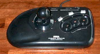
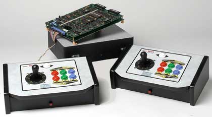
I decided to use Sega Megadrive "Arcade Power Stick" joysticks for my SuperGun for a few reasons:
- They have 3 fire buttons and a Start button - ideal for Jamma!
- They're solid and very sturdy
- They use a standard 9 pin D-type connector
- I had a couple laying around :-)
- They are fairly easy to get hold of (and cheap!) at "Cash Generator" type stores
Though I've used Megadrive joysticks, it would be just as easy to use controllers from any other console. All you need is a circuit which will de-multiplex the buttons and directions into separate signals.
Don't ask me how to design these for any other console because I just don't know how! I don't even own any controllers from any other console, I had these Megadrive ones from my Amiga days.
If you have designed or know where to find the plans for such a circuit for any other console then let me know and I can incorporate it here.
Using Megadrive (Genesis) Joysticks
Like me, you may have some old 4 button Megadrive Arcade joysticks laying about, or you may know where you can pick some up cheaply. (Note - The circuit described here will only decode the 4-button MegeDrive joysticks. If you use it with a 6-button stick then only the A, B, C and Start buttons will be useable). I had two of the sticks pictured here from my old Amiga days, I never actually owned a Megadrive itself.
These are tough and durable "
The only problem is that the four fire button signals are multiplexed down two pins, so we have to build a small circuit to decode them. You could, of course, use Megadrive joypads with this circuit, but I strongly recommend you get an arcade style joystick like the one above - you should at least try to retain *some* of the arcade feel!
The next set of pages describe how to build a circuit which will decode the joystick functions so that we can use them on our SuperGun. Descriptions of how the circuit works are also included for those of you who are interested.
If you're not adept at soldering then don't panic! The circuit is very easy to build and won't cost much. If you have / can get hold of Megadrive joysticks then this is a much cheaper option than custom building your own arcade joysticks.
How Megadrive joysticks work
The pins on the joystick connector have the following assignments:
Pin |
Connection |
1 |
Up |
2 |
Down |
3 |
Left |
4 |
Right |
5 |
Power (+5v) |
6 |
Buttons “A” and “B” |
7 |
Select |
8 |
Ground (0v) |
9 |
Buttons “C” and “Start” |
When a button or direction is not pressed, the corresponding pin will be at +5v (logic high). When a button or direction is pressed, the corresponding pin will be at 0v (logic low). As you can see, pin 6 reflects the state of both button "A" and button "B", and pin 9 the state of both button "C" and the "Start" button. Exactly which button is connected to these pins at any given point in time is determined by the status of the select signal, on pin 7:
Pin |
With Select High |
With Select Low |
1 |
Up |
Up |
2 |
Down |
Down |
3 |
Left |
Ground (0v) |
4 |
Right |
Ground (0v) |
5 |
||
6 |
Button “B” |
Button “A” |
7 |
||
8 |
||
9 |
Button “C” |
Button “Start” |
As it happens the Left and Right signals are also multiplexed, being connected to 0v when the select signal is low and reflecting the status of the Left and Right directions when the select signal is high. We will take this into account in our circuit.
Normally, the Megadrive game program will have a subroutine which will set the select pin high or low depending on which button or direction it wants to check the status of. Obviously, Jamma games don't do this, so we must devise our own solution :o)
How the circuit will work
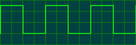
For starters, it's fairly obvious that we're going to need a "clock" signal to act as the select pin. For this we will generate a square wave with a 1:1 mark/space ratio.
We first generate a clock signal using a simple 555 timer, connected as an oscillator. I chose component values which give a clock frequency of approx. 100Hz. The output from this will look something like this:
This doesn't have a 1:1 mark/space ratio, the signal would favour reading buttons "B" and "C" as it is high most of the time and only low briefly. We will square it up by feeding it through a D-Type latch configured as a toggle flip-flop. The output of the flip-flop will change to the opposite state every time the clock signal goes high, and will look like this:
 As you should be able to see, the signal output by the flip-flop
changes state at the same instant the original clock signal above goes high.
Here are both waveforms pictured together for clarity:
As you should be able to see, the signal output by the flip-flop
changes state at the same instant the original clock signal above goes high.
Here are both waveforms pictured together for clarity:
This gives a perfect square wave with half the
frequency of the original signal (so it's now about 50Hz). As a bonus, the
flip-flop also has an inverted output which we will put to good use in our
circuit. This signal will be connected to the select pin of the joystick and
will also be used to decode the joystick inputs.
Now that we have our clock signal we need to decode the joystick inputs. We can do this using D-Type latches. A D-Type latch is activated when the clock signal fed to it goes high. During this period it will look at the input pin and will set the output pin to the same value. This value will stay on the output pin until the input is re-sampled when the clock goes high again.
How the circuit
will work (Continued)
If we have two D-Type latches, one being fed the
clock signal and one being fed the inverted clock signal, then one will be
active when the clock goes high and one when the clock goes low. So, to decode
buttons "A" and "B" we simply connect the "button
A/B" signal to the input of each of these two latches. The latch which
activates when the clock goes high (same as select goes high) will output the
status of button "B" and the latch which activates when the clock
goes low (same as select goes low) will output the status of button
"A". We repeat this for the "button C/Start" signal using
two more latches. Fortunately, D-Type latches come in a chip (a 74LS175 or
equivalent) containing 4 latches, so two such chips gives us exactly enough
latches to decode the fire buttons of 2 joysticks.
We also need to consider the left and right signals. The pins for left and right on the joystick only reflect the status of the left and right directions when the select signal is high, when the select pin is low they output 0v. Again we can feed the left and right pins into a D-Type latch (one for left, one for right), this time we only need one which is activated when the clock (or select) goes high as we don't care about the output of these pins when the select line goes low. One 74LS175 will again provide exactly the right number of latches to decode the left and right directions of two joysticks.
Building the circuit
I designed and built this circuit using parts I had laying around, so there may well be better and more economic ways of doing the same thing. Feel free to make any suggestions...The circuit uses the following parts:
Part |
Qty |
Description |
IC1 |
1 |
555 timer |
IC2,3,4,5 |
4 |
74LS175 Quad D-Type latch (or equivalent) |
1 |
8 pin DIL IC socket |
|
4 |
16 pin DIL IC socket |
|
C1 |
1 |
15uF capacitor |
C2 |
1 |
0.1uF disc capacitor |
R1 |
1 |
27k resistor |
VR1 |
1 |
100k variable resistor |
CN1,2 |
2 |
9 pin D-type plugs |
1m |
Thin wire (for making links on the PCB) |
|
1 |
stripboard, at least 14 x 52 holes |
If you work with PC's, have access to PC spares or frequent computer fairs you may find the following of some use:
For the 9-pin D-Type joystick connectors I used two mouse serial connectors salvaged from old I/O cards. These also come with a ribbon cable attached, but you should check which wire goes to which pin as I have found two different wiring schemes.
For connecting power to the board, I used a 5.25" to 3.5" power connector adapter (for connecting a 3.5" floppy to a hard drive style power connector) and cut off the 3.5" end. This left a 5.25" power connector socket on one end and two wires on the other, which I soldered to the PCB. This way you can power the circuit from the PC PSU without having to alter the PSU at all.
I built my prototype on a piece of stripboard 14x52 holes. You first need to cut a few tracks, as indicated in the diagram below. Note - This is viewed from the copper side of the board
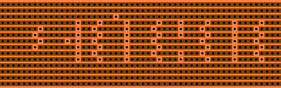
Once you've cut the tracks indicated, you can
solder the components and links into place, as indicated below. This one is
viewed from the component side. I'd recommend you start
by soldering the IC sockets in place first (or the IC's themselves if you're
that confident :o) as they're quite easy to position - each one straddles a
zig-zag of cut tracks. Note that the track between the top two pins of IC2-IC5
is not cut. Once they're in place it should be easier to position the other
components and links relative to them.
Building the circuit (Continued)
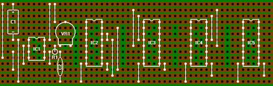
So far so good. The variable resistor VR1 can be
used to adjust the frequency of the clock. At about the mid position the clock
circuit will output a square wave with a frequency of about 50Hz, which seems
to work well. Should you experience problems then you could try adjusting the
variable resistor. Note the other resistor (R1) is mounted in the upright
position.
All we need to do now is connect up the power, the inputs from the joystick and the outputs to the Jamma connector.
Building the circuit (Cont) - connecting the inputs and outputs
You should now have a pretty neat little circuit board, but now things get a bit untidy :-) We need to connect the inputs from the megadrive joysticks to the circuit and tap off the decoded outputs, which will go to the Jamma board. If we had a custom etched PCB we could position all the outputs together in a tidy group, but the only way to do it when working with stripboard is to connect the wires directly to the relevant points on the board, so that's what we'll do.
The diagram below shows where we connect up CN1 and CN2, the joystick connectors for players 1 and 2. (the clock part of the circuit has not been drawn for clarity).

The connections drawn in blue go to CN1, which will be the joystick connector for player 1. The red connections are made to CN2, the joystick connector for player 2.
Now all we need to do is connect up the decoded outputs, which will eventually go to the Jamma connector. The wires connecting CN1 and CN2 have not been shown in this diagram for clarity, but the positions where they are soldered have been left marked for reference.
Building the circuit (Cont) - connecting the inputs and outputs

Don't forget that the Up and Down functions were not encoded and should be connected directly to pins 1 and 2 of CN1 (for player 1) and CN2 (for player 2). I would recommend that these outputs are made to an 8-way molex connector or perhaps a piece of terminal block, that way the circuit can easily be removed if necessary and a different input module could easily be connected to the supergun. Actually, had I used a slightly larger piece of stripboard (16 strips and a few holes longer) I could have routed the outputs to 2 molex connectors soldered directly to the stripboard... To connect the circuit to the SuperGun we just need to attach these connectors to the signals going to the player inputs on the Jamma connector.
Last of all, we need to connect power to the circuit. I used a connector which mates to a hard drive type power connector on a PC, which makes it easy to connect and remove the circuit. You could cut the connector off the end of a PC power supply and solder the +5v and 0v directly to the board, but that is a bit permanent.
The circuit operates on +5v, which should be connected to the top rail. 0v is connected to the bottom rail.
Building
the circuit (Cont) - connecting the inputs and outputs
That's it! All that remains is to connect it up to the Supergun.
I am sure that this circuit could be improved or an equivalent made using less parts (e.g. using 2 hex D-type latches instead of 3 quads would save one IC). I do not class myself as an electronics wiz, I initially decided to make this circuit just to see if I could and I used parts I already had laying around. If you feel you can improve the design or point me to a better on then please feel free to do so.
Housing the Jamma Box
That's it for the wiring. You can now tie all the bundles of wire together with cable ties or similar to create the Jamma Loom.
Now you'll need to house it a nice box. Mine hasn't been housed yet so I can't show you what I've done, but here's the general idea:
The PSU and piece of stripboard we used can be completely enclosed. Trail the Jamma Loom and any other minor looms for extra fire buttons or extra player joysticks out of one side of the box through a cutout. Use cable ties or a grommet or some other means to help prevent damage to the wiring and to prevent it from being pulled out too far and hence possibly damaging the stripboard.
The video connector on the stripboard would ideally go to a panel mounting socket on the rear of the unit somewhere - you could use a 6-pin DIN socket or some other similar multiway connector, your choice of video lead would then plug into this socket. If you really wanted you could just connect the video cable itself to the stripboard and pass it through a hole in the case, but this makes the unit less flexible.
The joystick connectors could be fitted on the front panel somewhere, alongside the push buttons (if you fitted them) for the coin inputs and test switches. Give it a snazzy paint job and there you are!
Here are some more suggestions:
The commercial "SuperNova" supergun is housed in a big, rectangular box, slightly larger than an average Jamma PCB. This lets you sit the PCB on top of the unit when it's being played, which isn't a bad idea as it would take up less space this way, as well as preventing your dog or young kids from tripping over the PCB and unplugging it just as you're about to beat your highest ever score ;-).
Surely they should have made the wire to the PCB a bit longer...?
Make sure the top of the case you use isn't metal though, or you may have to insulate it from the bottom of the PCB (the feet from Jamma PCBs always seem to have gone astray long before you own the board :-)
Housing the Jamma
Box
Another idea is to house it in a carry case like those aluminium briefcases
that always bash your legs when you carry them. (I've shamelessly stolen this
idea from Lee
Richards, who has built a Jamma Box and housed it this way. Thanks Lee ;-)
This way you can sit the PCB in the lid of the case once it is opened out flat, and you should be able to mount the power supply and associated wiring in the base and hopefully still have room to store two joysticks. You would probably be able to store a couple of PCBs in the lid somewhere too if you had a deep enough case. A neat job would be to have only the connectors for the power lead and the video output visible on the outside of the case. This would make a truly portable solution. Obviously you'd have to make sure everything is well insulated if the inside of the case is aluminium too :-)
Known Documentation Issues
There are no known documentation issues at this time. However, if you do find something to be incorrect or missing, please email the details at Robert@jabba.demon.co.uk and I’ll update the document.
Thanks for your help,
Rob Hazelby (6th August 2005)