Ahh, I hadn't looked into the algorithm implementation in MAME. The MEM storage in MAME has nothing to do with what I was just talking about. They've implemented this MEM storage as something which actually holds over the output of a particular operator for each channel between samples. In MAME, portions of most of the algorithms are actually fed with the calculated MEM value from the previous sample. I'm definitely suspicious about that. I see no reason for this to occur, especially as the operator unit still has to calculate all 4 operators each sample anyway. It's making the device more complicated and less accurate for no good reason as far as I can see.
I can't confirm or deny this behaviour until I test for it. I was going to be doing smiliar tests on channel 1 self-feedback. I'll make sure I expand those tests to look for any "delayed sample" behviour from any of the operators. If you modified MAME to remove the MEM storage and it fixed the problem though, that's pretty strong evidence this delayed sample storage doesn't exist for algorithm 0 at least.
New Documentation: An authoritative reference on the YM2612
Moderator: BigEvilCorporation
Hi,
I think the delayed sample actually does exists (and its emulated in Regen). The reason? Well it will sound fine in Gens but if you listen very closely to the track 3 of Mega Turrican in Gens some instruments will come a bit early then they should be. Again, you should listen very carefully other wise you won't notice the difference.Here is a recording from the real hardware for the relevant part. I've only seen Regen and Kega that emulate it perfectly. I think its not related to delayed sample. I think it some kind of inaccuracy in envelope generator.
stay safe,
AamirM
The problem in MAME core with those tracks seems to be more related to feedback implementation, especially when the feedback value is 7... I re-tested and the MEM delayed sample has nothing to do with that, my bad...
About self-feedback, here is how I understand how it works according to the documentation:
for slot 1 only, the phase input of the sin tab can be added by a factor of the slot ouput :
S1(t) = E1(t) x sin (w1.t + B.S1(t))
The factor B is given by the following table, depending of the feedback register value:
About the feedback factor (or shift value), here is how I understand it:
the relation between frequency and phase is: w =2xPIxfreq
this would mean the B factors (shifts) would be, in term of frequency (calculations in emulators are based on frequencies increment):
0, 1/32 (>>5), 1/16 (>>4), 1/8 (>>3), 1/4 (>>2), 1/2 (>>1), 1 (>>0) and 2 (<<1)
Now each core are dealing with this differently:
- gens core is doing PHASE += (OUT + OLD_OUT) >> FB
where FB = 9 - v
- Mame core is doing (only if v !=0) PHASE += (OUT + OLD_OUT) << FB
with FB = 6 + v
I guess the Gens core is translating the 13-bits OUT value is in a 10-bits phase value (>>3) then applying the feedback factor (see above)
I still don't understand the MAME implementation yet
ps: for the record, here is the US patent describing self-feedback:
http://www.google.com/patents?id=IeA3AAAAEBAJ
another one describing FM synth in detail:
http://www.google.com/patents?id=GNEzAAAAEBAJ
About self-feedback, here is how I understand how it works according to the documentation:
for slot 1 only, the phase input of the sin tab can be added by a factor of the slot ouput :
S1(t) = E1(t) x sin (w1.t + B.S1(t))
The factor B is given by the following table, depending of the feedback register value:
In an emulator, I initially thought a straight implementation was doing something like that, for each sample:v=0 -> B = 0
v=1 -> B = PI/16
v=2 -> B = PI/8
v=3 -> B = PI/4
v=4 -> B = PI/2
v=5 -> B = PI
v=6 -> B = 2.PI
v=7 -> B = 4.PI
but both MAME and GENS implementation use something more like :PHASE += OUT x feedback_factor
OUT = SIN_TABLE[PHASE][ENV]
probably it is more correct, I'm still not sure whyPHASE + (OLD_OUT + OUT) x feedfack_factor
OUT = OLD_OUT
OLD_OUT = SIN_TABLE[PHASE][ENV]
About the feedback factor (or shift value), here is how I understand it:
the relation between frequency and phase is: w =2xPIxfreq
this would mean the B factors (shifts) would be, in term of frequency (calculations in emulators are based on frequencies increment):
0, 1/32 (>>5), 1/16 (>>4), 1/8 (>>3), 1/4 (>>2), 1/2 (>>1), 1 (>>0) and 2 (<<1)
Now each core are dealing with this differently:
- gens core is doing PHASE += (OUT + OLD_OUT) >> FB
where FB = 9 - v
- Mame core is doing (only if v !=0) PHASE += (OUT + OLD_OUT) << FB
with FB = 6 + v
I guess the Gens core is translating the 13-bits OUT value is in a 10-bits phase value (>>3) then applying the feedback factor (see above)
I still don't understand the MAME implementation yet
ps: for the record, here is the US patent describing self-feedback:
http://www.google.com/patents?id=IeA3AAAAEBAJ
another one describing FM synth in detail:
http://www.google.com/patents?id=GNEzAAAAEBAJ
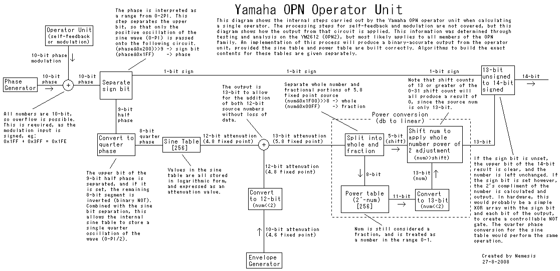
Well, I can't answer the questions about self-feedback yet. I haven't started doing any serious testing of self-feedback, but when I do, I'll definitely investigate these issues and see if I can track down the cause. I can post a lot of info about other aspects of the operator unit however. They should be an interesting read for someone. I've also finished my testing on the phase generator and accumulator. I'll write up my findings in those areas once I've got some time free. Until then, here's the OPN operator unit in a nutshell.
The core of the operator unit is the process involved in evaluating a single operator. That process involves taking a 10-bit output from the envelope generator, a 10-bit output from the phase generator, a 10-bit phase modulation input (generated by the operator unit itself from either self-feedback or modulation by another operator), and producing a single 14-bit result, which is then either output to the accumulator or used to modulate another operator. The steps involved in generating this 14-bit output are IMO the most poorly expressed and documented parts of the MAME core, and you'd be hard pressed to figure out what was going on by looking at the MAME implementation alone.
There's one very important thing to note before I say anything more about the operator unit. There's a very big lie in all of the OPN documentation. You will read time and time again that the envelope generator has the power to attenuate the output by between 0db and 96db. This is incorrect. In fact, the envelope generator can only attenuate the output by 0db to 48db. This doesn't change anything about how you implement the envelope generator itself, but for every table you see in any documentation that discusses decibels, you need to divide every value by 2 to get the real attenuation values. TL is actually 0-48db. SL is actually 0-12db (or 48db when all set), and the 10-bit output of the envelope generator itself is of course 0 to 48db. There wouldn't be much point in giving the envelope generator a 96db range. The output of the OPN operator unit is only 14-bit, and lacks the resolution required in order to represent numbers over around 40db attenuation anyway. Anything past that point just outputs 0, so they couldn't have implemented a 96db effective range without a significant increase in the precision of the operator unit.
On paper, the calculations the operator unit performs are simple. The operator unit simply has to calculate the sine value for the phase, and attenuate it by the output from the envelope generator. That's it. You could implement the operator unit like this:
This was actually my first implementation. It works, and if the YM2612 was a "perfect" device, this would actually be a very accurate implementation. In reality, Yamaha had to actually build the operator unit as a physical device, and they had to do it as cheaply and efficiently as possible, within the boundaries of what was possible with the technology of the time. The end-result is that the operator unit is not as precise as the calculation which is performed above. I doubt you'll hear any audible difference, but if you want to build an accurate emulator, it is possible to perfectly emulate the operator unit calculations performed by the YM2612, but the implementation is a little more complex than the algorithm I've just presented.
I've done a lot of analysis and testing, and I've figured out what I believe are the exact steps the real operator unit performs. I can guarantee if you follow the information I'm about to show, you will be able to create a 100% binary exact implementation of the YM2612 operator unit. I've implemented all of this in my YM2612 core, and it works a treat. It is worth noting that MAME already gets a 100% accurate output for this area, though the implementation is a little hard to understand.
I found the easiest way to document the core of the operator unit was using a diagram. They say a picture says a thousand words, so hopefully this will save me some typing:
Here's my (heavily commented) algorithm to build the perfect contents for the sine table:
And here's my algorithm to build the perfect contents for the power table:
I'd also suggest you wrap the entire power conversion into a function like this:
A quick note about fixed point, in case you've never encountered that term before. What "fixed point" means is that a number is an integer value, but one or more of the bits in the number are treated as if they were after the decimal place, so you could represent non-whole numbers like 3.6 or 1.5. In the case of a 4.8 fixed point number, the upper 4 bits are used to represent the whole number portion, while the lower 8 bits are used to represent the "fractional" portion below the decimal place, meaning 1.5 would be represented by 0x180 for example. You'll see that the operator unit uses fixed point math when handling attenuation values.
Everything you should need to implement a perfect operator unit is shown above. What I'm going to do now is simply talk about how the actual implementation created by Yamaha relates to the "perfect" algorithm shown right at the start, so you can understand why the Yamaha implmentation works. You'll need to be clear on logarithms first of all. I find it easiest to think of a logarithm as the "reverse" of a power function, so:
10^log10(num)=log10(10^num)=num
The envelope generator output is represented in decibels. Decibels are a 10th of a "bel", so a value of 48 decibels is 4.8 bels. Bels are a value on the base 10 logarithmic scale. This means in order to convert back to a linear value, we would need to use a pow10 function, or 10^num, where num is a base 10 number representing a value in bels. In the case of attenuation, you could calculate 10^-num to get a normalized representation of the attenuation in the linear scale. In the first algorithm I presented, this is exactly what we did. The 10-bit attenuation output from the envelope generator was scaled to a floating point value between 0 and 4.8, and converted to a linear normalized result.
Yamaha don't do this in the YM2612. Instead, they use a useful property of logarithms to reduce the work the operator unit has to do. Logarithms reduce multiplication down to addition. As you'll find right near the top of the wiki article, log(x * y) = logx + logy. Yamaha took advantage of this fact when designing the OPN operator unit. Rather than convert the attenuation from the envelope generator into a linear scale and multiply it with the output from the sine table, they converted the sine table itself to return values which are also a logarithmic representation of attenuation. This allowed them to simply add the two numbers together, then convert the whole thing back to a linear scale to get the final output, doing away with the need for multiplication. This is the reason the sine table in the YM2612 is built in a non-standard way, it's the reason the power conversion happens after the sine value is attenuated by the envelope generator output, and it's the reason the attenuation from the envelope generator and the output from the sine table are simply added together.
There's one remaining quirk about the implementation which needs explanation, and that's all about bases. In the algorithm I presented at the start, we convert the envelope generator output to an expression of attenuation in bels, then use a base 10 power function to convert from bels, which is a base 10 logarithmic scale, to a linear value. You'll see the Yamaha implementation uses a base 2 power function to convert back to a linear value however. That's not a problem for the sine table, as you'll see in the comments for building the sine table that we (effectively) use a base 2 log function to build the table, so the base 2 power function is the valid conversion to turn those back to linear values. What about the envelope generator output though? We talk about the attenuation of the envelope generator in decibels, and doesn't that require a base 10 power function to convert back to a linear scale?
First of all, here's the weighting table I gave previously for the 10-bit envelope generator output:
Given that the official documentation is incorrect, and that the output of the envelope generator is 0-48db, this is the actual weighting of each bit of the output:
You can see from the diagram above that I indicate this 10-bit output is also actually a 4.6 fixed point value, like so:
First of all, you'll note that these numbers are not in base 10 at all. Bit 6, which is the first "whole number" bit of the output, actually has a reported weighting of 3db. If this was a base 10 number, 3db would be represented by a whole number value of 0x03, not 0x01, and 24db would be represented by a whole number value of 0x18, whereas here it's 0x08.
To understand what's going on here, have a look at the code to build the sine table. We need to calculate a log2 value, but there's only a log10 function available. We can in fact convert a log10 value into a log2 value using a useful identity however. As presented in the comments, that identity as it applies to this case is as follows:
2^(log10(x)/log10(2))=2^log2(x)=x
In more general terms, if you divide the result of logx(num) value by logx(y), where x and y are two arbitrary bases, you convert bases, giving you the same result as logy(num).
What that means is that if we wanted to convert from base 10 logarithmic values, that being the attenuation in bels in this case, into base 2 logarithmic values, we would have to divide the base 10 logarithmic value by log10(2). So, what is the value of log10(2)? Well, it's approximately 0.30103. That's fairly close to 0.3. The guys at Yamaha decided it was close enough. First of all, let's convert our attenuation values from decibels to bels, by simply dividing all the numbers by 10:
Now look what happens when we divide all those numbers in our weighting table by 0.3:
Now we see what we've actually got is straight values in powers of 2. This shows the output from the envelope generator is in fact a base 2 logarithmic expression of attenuation, and we can see from the table above it is in fact in 4.6 fixed point form, so we just need to convert it to 4.8 fixed point form, and it's ready to be combined with the output from the sine table.
And I think that's everything there is to know about how an operator is calculated. The only other parts of the operator unit which remain relate to how the phase modulation input is calculated for self-feedback and modulation.
The core of the operator unit is the process involved in evaluating a single operator. That process involves taking a 10-bit output from the envelope generator, a 10-bit output from the phase generator, a 10-bit phase modulation input (generated by the operator unit itself from either self-feedback or modulation by another operator), and producing a single 14-bit result, which is then either output to the accumulator or used to modulate another operator. The steps involved in generating this 14-bit output are IMO the most poorly expressed and documented parts of the MAME core, and you'd be hard pressed to figure out what was going on by looking at the MAME implementation alone.
There's one very important thing to note before I say anything more about the operator unit. There's a very big lie in all of the OPN documentation. You will read time and time again that the envelope generator has the power to attenuate the output by between 0db and 96db. This is incorrect. In fact, the envelope generator can only attenuate the output by 0db to 48db. This doesn't change anything about how you implement the envelope generator itself, but for every table you see in any documentation that discusses decibels, you need to divide every value by 2 to get the real attenuation values. TL is actually 0-48db. SL is actually 0-12db (or 48db when all set), and the 10-bit output of the envelope generator itself is of course 0 to 48db. There wouldn't be much point in giving the envelope generator a 96db range. The output of the OPN operator unit is only 14-bit, and lacks the resolution required in order to represent numbers over around 40db attenuation anyway. Anything past that point just outputs 0, so they couldn't have implemented a 96db effective range without a significant increase in the precision of the operator unit.
On paper, the calculations the operator unit performs are simple. The operator unit simply has to calculate the sine value for the phase, and attenuate it by the output from the envelope generator. That's it. You could implement the operator unit like this:
Code: Select all
//attenuationBitCount = 10
//phaseBitCount = 10
//operatorOutBitCount = 14
//phase = the output from the phase generator
//attenuation = the output from the envelope generator

//Calculate the sine value
double phaseNormalized = ((double)phase / ((1 << phaseBitCount) - 1))
double sinResult = sin(phaseNormalized * M_PI * 2);

//Convert the attenuation to a linear representation of power
double attenuationIndividualBitWeighting = 48.0 / (1 << attenuationBitCount);
double attenuationInBels = (((double)attenuation * attenuationIndividualBitWeighting) / 10.0);
double powerLinear = pow(10.0, -attenuationInBels);

//Attenuate the result
double resultNormalized = sinResult * powerLinear;

//Calculate the 14-bit operator output
unsigned int maxOperatorOutput = ((1 << (operatorOutBitCount - 1)) - 1);
int result = (int)(resultNormalized * maxOperatorOutput);I've done a lot of analysis and testing, and I've figured out what I believe are the exact steps the real operator unit performs. I can guarantee if you follow the information I'm about to show, you will be able to create a 100% binary exact implementation of the YM2612 operator unit. I've implemented all of this in my YM2612 core, and it works a treat. It is worth noting that MAME already gets a 100% accurate output for this area, though the implementation is a little hard to understand.
I found the easiest way to document the core of the operator unit was using a diagram. They say a picture says a thousand words, so hopefully this will save me some typing:
Here's my (heavily commented) algorithm to build the perfect contents for the sine table:
Code: Select all
//sinTableBitCount = 8
//attenuationFixedBitCount = 8
for(unsigned int i = 0; i < (1 << sinTableBitCount); ++i)
{
	//Calculate the normalized phase value for the input into the sine table. Note
	//that this is calculated as a normalized result from 0.0-1.0 where 0 is not
	//reached, because the phase is calculated as if it was a 9-bit index with the
	//LSB fixed to 1. This was done so that the sine table would be more accurate
	//when it was "mirrored" to create the negative oscillation of the wave. It's
	//also convenient we don't have to worry about a phase of 0, because 0 is an
	//invalid input for a log function, which we need to use below.
	double phaseNormalized = ((double)((i << 1) + 1) / (1 << (sinTableBitCount + 1)));

	//Calculate the pure sine value for the input. Note that we only build a sine
	//table for a quarter of the full oscillation (0-PI/2), since the upper two bits
	//of the full phase are extracted by the external circuit.
	double sinResultNormalized = sin(phaseNormalized * (M_PI / 2));

	//Convert the sine result from a linear representation of volume, to a
	//logarithmic representation of attenuation. The YM2612 stores values in the sine
	//table in this form because logarithms simplify multiplication down to addition,
	//and this allowed them to attenuate the sine result by the envelope generator
	//output simply by adding the two numbers together.
	double sinResultAsAttenuation = -log(sinResultNormalized) / log(2.0);
	//The division by log(2) is required because the log function is base 10, but the
	//YM2612 uses a base 2 logarithmic value. Dividing the base 10 log result by
	//log10(2) will convert the result to a base 2 logarithmic value, which can then
	//be converted back to a linear value by a pow2 function. In other words:
	//2^(log10(x)/log10(2)) = 2^log2(x) = x
	//If there was a native log2() function provided we could use that instead.

	//Convert the attenuation value to a rounded 12-bit result in 4.8 fixed point
	//format.
	unsigned int sinResult = (unsigned int)((sinResultAsAttenuation * (1 << attenuationFixedBitCount)) + 0.5);

	//Write the result to the table
	sinTable[i] = sinResult;
}Code: Select all
//powTableBitCount = 8
//powTableOutputBitCount = 11
for(unsigned int i = 0; i < (1 << powTableBitCount); ++i)
{
	//Normalize the current index to the range 0.0-1.0. Note that in this case, 0.0
	//is a value which is never actually reached, since we start from i+1. They only
	//did this to keep the result to an 11-bit output. It probably would have been
	//better to simply subtract 1 from every final number and have 1.0 as the input
	//limit instead when building the table, so an input of 0 would output 0x7FF,
	//but they didn't.
	double entryNormalized = (double)(i + 1) / (double)(1 << powTableBitCount);

	//Calculate 2^-entryNormalized
	double resultNormalized = pow(2, -entryNormalized);

	//Convert the normalized result to an 11-bit rounded result
	unsigned int result = (unsigned int)((resultNormalized * (1 << powTableOutputBitCount)) + 0.5);

	//Write the result to the table
	powTable[i] = result;
}Code: Select all
unsigned int YM2612::InversePow2(unsigned int num) const
{
	unsigned int shiftCount = num >> powTableBitCount;
	unsigned int tableIndex = num & ((1 << powTableBitCount) - 1);
	unsigned int tableEntry = powTable[tableIndex];
	unsigned int outputShifted = (tableEntry << 2) >> shiftCount;
	return outputShifted;
}Everything you should need to implement a perfect operator unit is shown above. What I'm going to do now is simply talk about how the actual implementation created by Yamaha relates to the "perfect" algorithm shown right at the start, so you can understand why the Yamaha implmentation works. You'll need to be clear on logarithms first of all. I find it easiest to think of a logarithm as the "reverse" of a power function, so:
10^log10(num)=log10(10^num)=num
The envelope generator output is represented in decibels. Decibels are a 10th of a "bel", so a value of 48 decibels is 4.8 bels. Bels are a value on the base 10 logarithmic scale. This means in order to convert back to a linear value, we would need to use a pow10 function, or 10^num, where num is a base 10 number representing a value in bels. In the case of attenuation, you could calculate 10^-num to get a normalized representation of the attenuation in the linear scale. In the first algorithm I presented, this is exactly what we did. The 10-bit attenuation output from the envelope generator was scaled to a floating point value between 0 and 4.8, and converted to a linear normalized result.
Yamaha don't do this in the YM2612. Instead, they use a useful property of logarithms to reduce the work the operator unit has to do. Logarithms reduce multiplication down to addition. As you'll find right near the top of the wiki article, log(x * y) = logx + logy. Yamaha took advantage of this fact when designing the OPN operator unit. Rather than convert the attenuation from the envelope generator into a linear scale and multiply it with the output from the sine table, they converted the sine table itself to return values which are also a logarithmic representation of attenuation. This allowed them to simply add the two numbers together, then convert the whole thing back to a linear scale to get the final output, doing away with the need for multiplication. This is the reason the sine table in the YM2612 is built in a non-standard way, it's the reason the power conversion happens after the sine value is attenuated by the envelope generator output, and it's the reason the attenuation from the envelope generator and the output from the sine table are simply added together.
There's one remaining quirk about the implementation which needs explanation, and that's all about bases. In the algorithm I presented at the start, we convert the envelope generator output to an expression of attenuation in bels, then use a base 10 power function to convert from bels, which is a base 10 logarithmic scale, to a linear value. You'll see the Yamaha implementation uses a base 2 power function to convert back to a linear value however. That's not a problem for the sine table, as you'll see in the comments for building the sine table that we (effectively) use a base 2 log function to build the table, so the base 2 power function is the valid conversion to turn those back to linear values. What about the envelope generator output though? We talk about the attenuation of the envelope generator in decibels, and doesn't that require a base 10 power function to convert back to a linear scale?
First of all, here's the weighting table I gave previously for the 10-bit envelope generator output:
Code: Select all
EG attenuation output bit weighting = 96 / 2^10
---------------------------------------------------------------------------------
|   9   |   8   |   7   |   6   |   5   |   4   |   3   |   2   |   1   |   0   |
|-------------------------------------------------------------------------------|
|   48  |   24  |   12  |   6   |   3   |  1.5  |  0.75 | 0.375 | 0.1875|0.09375|
---------------------------------------------------------------------------------Code: Select all
EG attenuation output bit weighting = 48 / 2^10
----------------------------------------------------------------------------------
|   9   |   8   |   7   |   6   |   5   |   4   |   3   |   2   |   1   |   0    |
|--------------------------------------------------------------------------------|
|   24  |   12  |   6   |   3   |  1.5  |  0.75 | 0.375 | 0.1875|0.09375|0.046875|
----------------------------------------------------------------------------------Code: Select all
|------Whole number portion-----|---------------Fractional portion---------------|
----------------------------------------------------------------------------------
|   9   |   8   |   7   |   6   |   5   |   4   |   3   |   2   |   1   |   0    |
|--------------------------------------------------------------------------------|
|   24  |   12  |   6   |   3   |  1.5  |  0.75 | 0.375 | 0.1875|0.09375|0.046875|
----------------------------------------------------------------------------------To understand what's going on here, have a look at the code to build the sine table. We need to calculate a log2 value, but there's only a log10 function available. We can in fact convert a log10 value into a log2 value using a useful identity however. As presented in the comments, that identity as it applies to this case is as follows:
2^(log10(x)/log10(2))=2^log2(x)=x
In more general terms, if you divide the result of logx(num) value by logx(y), where x and y are two arbitrary bases, you convert bases, giving you the same result as logy(num).
What that means is that if we wanted to convert from base 10 logarithmic values, that being the attenuation in bels in this case, into base 2 logarithmic values, we would have to divide the base 10 logarithmic value by log10(2). So, what is the value of log10(2)? Well, it's approximately 0.30103. That's fairly close to 0.3. The guys at Yamaha decided it was close enough. First of all, let's convert our attenuation values from decibels to bels, by simply dividing all the numbers by 10:
Code: Select all
|------Whole number portion-----|----------------Fractional portion----------------|
------------------------------------------------------------------------------------
|   9   |   8   |   7   |   6   |   5   |   4   |   3   |   2   |   1    |    0    |
|----------------------------------------------------------------------------------|
|  2.4  |  1.2  |  0.6  |  0.3  |  0.15 | 0.075 | 0.0375|0.01875|0.009375|0.0046875|
------------------------------------------------------------------------------------Code: Select all
|------Whole number portion-----|---------------Fractional portion---------------|
----------------------------------------------------------------------------------
|   9   |   8   |   7   |   6   |   5   |   4   |   3   |   2   |   1   |   0    |
|--------------------------------------------------------------------------------|
|   8   |   4   |   2   |   1   |  0.5  |  0.25 | 0.125 | 0.0625|0.03125|0.015625|
----------------------------------------------------------------------------------And I think that's everything there is to know about how an operator is calculated. The only other parts of the operator unit which remain relate to how the phase modulation input is calculated for self-feedback and modulation.
-
King Of Chaos
- Very interested
- Posts: 273
- Joined: Fri Feb 29, 2008 8:12 pm
- Location: United States
-
TulioAdriano
- Very interested
- Posts: 81
- Joined: Tue Jul 10, 2007 7:45 pm
- Location: Brazil / USA
- Contact:

-
King Of Chaos
- Very interested
- Posts: 273
- Joined: Fri Feb 29, 2008 8:12 pm
- Location: United States
Hi,
Nemesis, thanks a lot for the detailed description on operator unit. I have now fixed all the tables in my YM2612 core according to your tests and it has fixed a lot of sound issues in my core. As you said, MAME implementation wasn't clear (though it itself was 100% correct) so I was doing some wrong calculations which resulted in incorrect sound in many games (Urban Strike intro, Sonic 1/2/3/Knuckles special stages etc..) had a pop/crackle. I was thinking I had done them right (as MAME/docs say) but I didn't. Now thanks to you, I have just fixed it . The bug is most apparent in Sonic 3 (Angel Island Zone Act 2) when plane drops the bombs. Listen to it in the latest beta 3, the sound is distorted a lot.
Thanks again.
AamirM
Nemesis, thanks a lot for the detailed description on operator unit. I have now fixed all the tables in my YM2612 core according to your tests and it has fixed a lot of sound issues in my core. As you said, MAME implementation wasn't clear (though it itself was 100% correct) so I was doing some wrong calculations which resulted in incorrect sound in many games (Urban Strike intro, Sonic 1/2/3/Knuckles special stages etc..) had a pop/crackle. I was thinking I had done them right (as MAME/docs say) but I didn't. Now thanks to you, I have just fixed it
Thanks again.
AamirM
Hi,
Although I cannot confirm this but a Regen user has reported that track 12 in BattleTech does not sound like real hardware. And guess what, that track is reproducing GEMS bug but yet it does not goes into high frequency in the real hardware. Again, this needs to be confirmed. Only Gens plays this track correctly according to his recordings because it does not handle the GEMS bug.
stay safe,
AamirM
Hi,
The same user has also sent in another interesting thing. He has reported that the sound in the first stage of "Spider-Man and Venom - Separation Anxiety" doesn't sound correct in any emu except Kega (and later I found out that it was correct in the same VGM plugin by blargg ). So I guess there is an overflow again somewhere but I couldn't find any myself after a quick look.
stay safe,
AamirM
The same user has also sent in another interesting thing. He has reported that the sound in the first stage of "Spider-Man and Venom - Separation Anxiety" doesn't sound correct in any emu except Kega (and later I found out that it was correct in the same VGM plugin by blargg
stay safe,
AamirM
The sound issue in the first level of Separation Anxiety seems to be a self-feedback related issue, or at least it has similar symptoms to track 3 in Mega Turrican. I don't think it's related to detune. I'll be carrying out some tests to try and isolate this problem, and track down the cause. The title screen music has a separate issue however, one that is related to detune overflow. If you compare Kega and Regen, you'll hear the differences.
As for Battletech, I'll try it out on the actual hardware this afternoon. I can hear that Regen and Kega are getting a different result though. It's probably just an accuracy issue with how the overflow has been implemented in Regen, Kega, or both.
I should buckle down and write up my notes on the phase generator. There's no reason we can't get detune overflow perfect, and it seems like a lot of games rely it.