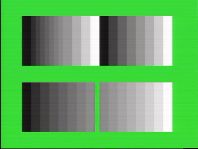
ok, I figured out, the color codes used in the test program (upper left window) have the same intensity in highlight and normal mode, that's why you don't see differences on real hardware.Eke wrote:I think the upper left is mixing shadow with normal then highlight with normal using pixel special codes to get a 16 (not 17) color gradient. However, it seems it does not work on real hardware as expected and highlight mode is not set for colors 0-7. Sourcecode would be useful hereYeah. I notice that too: not symmetric ladder. Why? Take a look at Gens! it's very strange...
The reason is that emulators (Kega as well but it got colors better than Gens) are wrong about colors in highlight mode. They probably add 8 to the 3-bits value like genesis plus did, the result is that colors go out of range (8-15 in the below table) and does not match normal colors as they should, which, as showed by the signal outputs, is wrong (highlight min & max values are resp. equal to shadow & normal max values).
If I use this instead:
i got correct results:/* normal mode : xxx0 (0-14) */
/* shadow mode : 0xxx (0-7) */
/* highlight mode: 1xxx - 1 (7-14) */
/* */
/* with xxx0 = original 4-bits CRAM value */

Another interesting thing is that Charles mentionned in his docs that the overscan area was always displayed at shadow intensity when the STE bits was set, however it does not seem to be the case here (top and bottom borders are shown at normal intensity). Maybe it's something particular to PAL ?


