New Documentation: An authoritative reference on the YM2612

For anything related to sound (YM2612, PSG, Z80, PCM...)

Moderator: BigEvilCorporation

Aly James
Very interested
Posts: 74
Joined: Sun Mar 31, 2013 11:34 pm
Location: FRANCE
Contact:

Post by Aly James » Fri May 31, 2013 8:26 pm

About the LADDER effect...
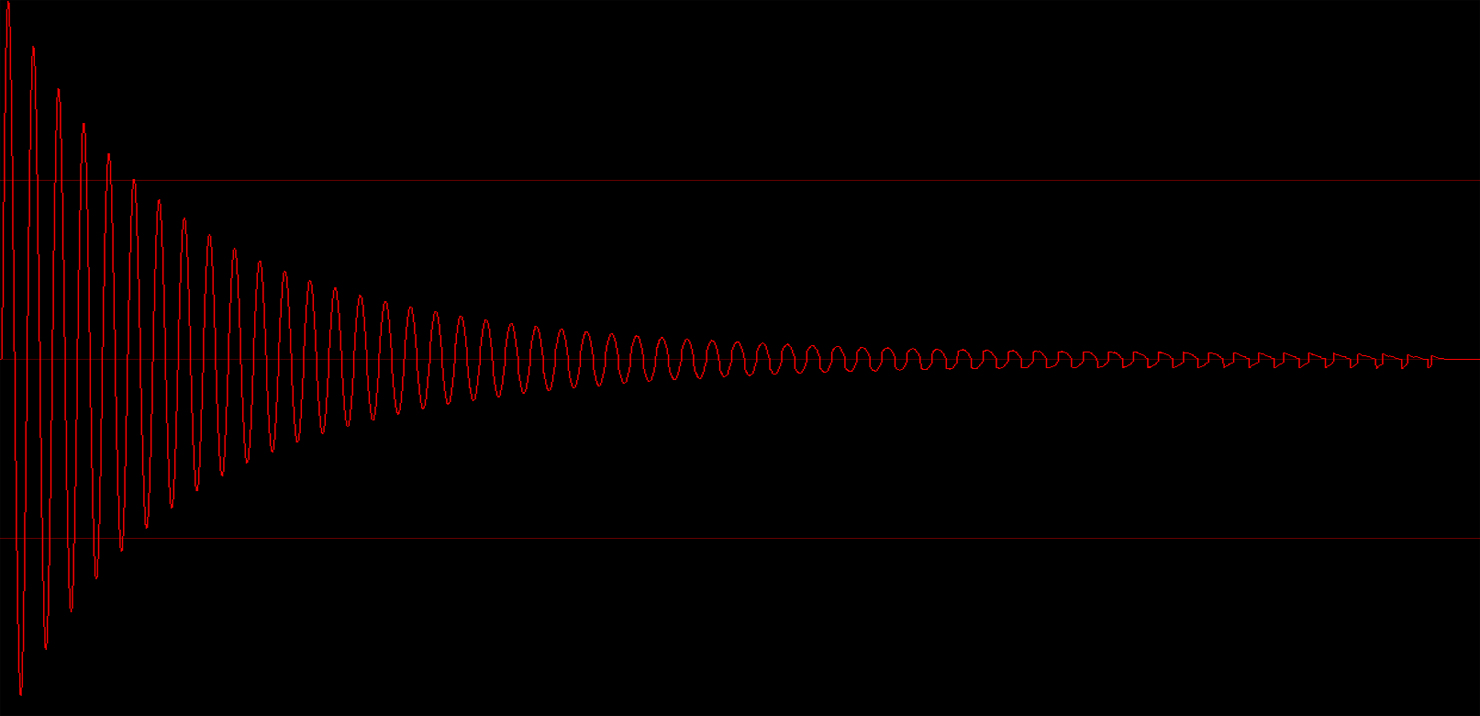
As previously stated in the FMDrive Vst thread, a simple way to implement the ladder effect is to add the clean output with the following...
(same behavior is observed on the hardware when you mute a channel, you still ear the distorted part at lower volume..)
This will produce an almost similar signal, spectrum and sound wise.
WAV recordings:
Megadrive PAL model 1 recording

FMDrive MD1 mode recording

and for the sake of comparison here is a clean signal from a YM2164 (from a FB01 unit)

We will do something when the output is negative...
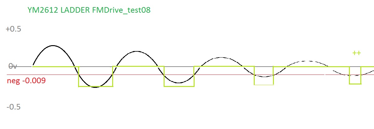
--------------------------------------------------------------------------------------
Ladder output:
-Let's consider the pure clean sine wave signal is going from max +1 to -1
as "sineout"
-Make a condition:
If sineout goes down past -0.009 then output a negative voltage almost 50 times lower then the clean maximum signal.
Else output 0.0 (and this will also prevent audio clicks)

Now let's see what happens to the "Ladder output"...
As you can see on the graphic, as the amplitude of the sine goes much lower, the period where the condition is true will also reduce..and this is what we clearly ear at the end.
green is our "Ladder output".

Image

Note that you will also need to filter a bit (lp filter) the ladder output before adding to the clean signal.

Code snippet from FMDrive..
If you make any use of this, credit would be nice ;)

Code: Select all

//Start of very fast ladder code 
while( --sampleFrames >= 0 )  // sampleFrames = how many samples to process (may change). repeat (loop) that many times
	{
		    sineout = *in; // max -1 +1

   //ladder condition, VCC or GROUND

 if (sineout<-0.009f)
{ladder=-0.02f;               // output is almost 50 times lower than the clean signal, can be adjusted or optionally controlled..

 }
 else
 ladder=0.0f; // grounded no signal


*ladder_out = ladder;  //then filter this before adding to sineout

 ladder_out++;

 in++;

}
Here you can see a very fast decay envelope that kind of shows the process :)
Image

trap15
Newbie
Posts: 1
Joined: Sat Sep 28, 2013 9:40 pm

Post by trap15 » Sat Sep 28, 2013 9:53 pm

I know this was asked earlier, but the answer wasn't exactly clear.

I've been working on a YM2203 emulator (yes, not quite a YM2612, but most everything else here has been extremely helpful and accurate, so I have no reason to believe that this is different), and I've run into an interesting concern.

If I update the EG counter on every "output cycle", the EG is too fast. Here's what that update process looks like:

Cycle 0: Update output latch, increment EG counter, Update Op0 of Chan0
Cycles 1-3: Update Op[2,1,3] of Chan0
Cycles 4-7: Update Op[0,2,1,3] of Chan1
Cycles 8-11: Update Op[0,2,1,3] of Chan2

Now, if I modify my code to update the EG every 3 "output cycles", the EG seems to be updating at the proper rate. Here's what that looks like:

Cycle 0: Update output latch, increment EG counter, Update Op0 of Chan0
Cycles 1-3: Update Op[2,1,3] of Chan0
Cycles 4-7: Update Op[0,2,1,3] of Chan1
Cycles 8-11: Update Op[0,2,1,3] of Chan2
Cycle 12: Update output latch, Update Op0 of Chan0
Cycles 13-15: Update Op[2,1,3] of Chan0
Cycles 16-19: Update Op[0,2,1,3] of Chan1
Cycles 20-23: Update Op[0,2,1,3] of Chan2
Cycle 24: Update output latch, Update Op0 of Chan0
Cycles 25-27: Update Op[2,1,3] of Chan0
Cycles 28-31: Update Op[0,2,1,3] of Chan1
Cycles 32-35: Update Op[0,2,1,3] of Chan2


Considering that this works and sounds correct, I'm willing to bet it's the correct (or at least similar to the correct) functionality. However, I'm not quite sure how or why, and I doubt the accuracy of it as well. I'd really appreciate any insight or information for this.

A little side question as well, and not nearly as important, is what order the updates occur in. As in, is the output latch updated on cycle 0, or cycle 11? Is the EG counter updated on cycle 0, or cycle 11 (or 35 or whatever)?

Aly James
Very interested
Posts: 74
Joined: Sun Mar 31, 2013 11:34 pm
Location: FRANCE
Contact:

Post by Aly James » Tue Oct 01, 2013 9:31 am

IIRC EG updates every 3 FM update cycles..

Mamizou
Interested
Posts: 25
Joined: Thu Apr 19, 2012 4:50 pm
Contact:

Post by Mamizou » Sun Nov 03, 2013 5:27 am

Just a heads up, someone at siliconpr0n.org decapsulated a YM3438 and did high-res scans of the metal layer. It's definitely a different layout than the YM2612, although the typical YM chip functional blocks are still recognizable.

Looks like the EG was shifted to being 'below' the ROMs instead of off to the opposite side of the PG (assuming 'top' is to the left on the scan, so it's comparable to the YM2612 scan). Probably so there's less trace distance between those functional blocks. The DAC is still in the 'upper-right' (upper-left of the scan).

TmEE co.(TM)
Very interested
Posts: 2442
Joined: Tue Dec 05, 2006 1:37 pm
Location: Estonia, Rapla City
Contact:

Post by TmEE co.(TM) » Sun Nov 03, 2013 6:15 am

That is awesome ! It looks quite a bit different from 2612.

I have been adding SSG-EG to my YM core, that is going somewhat well. I'll likely have questions about it later on.

LFO info never really appeared here, so, will it appear here ?
Mida sa loed ? Nagunii aru ei saa ;)
http://www.tmeeco.eu
Files of all broken links and images of mine are found here : http://www.tmeeco.eu/FileDen

Nemesis
Very interested
Posts: 791
Joined: Wed Nov 07, 2007 1:09 am
Location: Sydney, Australia

Post by Nemesis » Sun Nov 03, 2013 11:12 pm

I just don't have time to write up info on it right now, and I've probably forgotten half of it anyway, but I'm working towards the source release of my emulator Exodus, which has my heavily commented YM2612 core in it, so you'll be able to refer to that soon as a working reference model. I wrote that core in tandem with my testing and findings, verifying the output to the chip on many points, including the LFO. That said, I think there were one or two questions I had remaining about the LFO I never got back to testing. If so, those questions should appear as comments in my source marked with //##TODO## or //##FIX##.

TmEE co.(TM)
Very interested
Posts: 2442
Joined: Tue Dec 05, 2006 1:37 pm
Location: Estonia, Rapla City
Contact:

Post by TmEE co.(TM) » Mon Nov 04, 2013 1:05 am

OK, I shall wait for that time then.

It is very hard for me to get any info from the existing implementations, they are written is totally different way than I have done with like 3x more code... (2K vs ~600 lines)
Mida sa loed ? Nagunii aru ei saa ;)
http://www.tmeeco.eu
Files of all broken links and images of mine are found here : http://www.tmeeco.eu/FileDen

HardWareMan
Very interested
Posts: 746
Joined: Sat Dec 15, 2007 7:49 am
Location: Kazakhstan, Pavlodar

Post by HardWareMan » Sat Oct 25, 2014 3:36 pm

New osc - new pictures.
Image
Image
Image
Image
Image
Yellow - phones left
Cyan - phones right
Magenta - YM2612 output
That's what I'm talking about from beginning. You can clearly see how filtering works.

Battletech, music 12 (that sound):
Image
Image
Image
Image
Image
Image
Image
Image

MintyTheCat
Very interested
Posts: 484
Joined: Sat Mar 05, 2011 11:11 pm
Location: Berlin, Germany

Post by MintyTheCat » Sat Oct 25, 2014 7:45 pm

A question:

What are the RIGOL Scopes like? I had some reservations personally but are they any good? Which Scope are you using?
UMDK Fanboy

HardWareMan
Very interested
Posts: 746
Joined: Sat Dec 15, 2007 7:49 am
Location: Kazakhstan, Pavlodar

Post by HardWareMan » Sun Oct 26, 2014 2:07 am

MintyTheCat wrote:A question:

What are the RIGOL Scopes like? I had some reservations personally but are they any good? Which Scope are you using?
Previously, I used this one: http://www.rigol.com/prodserv/DS1000E/
Now I use this one: DS1074Z-S http://www.rigol.com/prodserv/DS1000Z/

MintyTheCat
Very interested
Posts: 484
Joined: Sat Mar 05, 2011 11:11 pm
Location: Berlin, Germany

Post by MintyTheCat » Sun Oct 26, 2014 11:55 am

HardWareMan wrote:
MintyTheCat wrote:A question:

What are the RIGOL Scopes like? I had some reservations personally but are they any good? Which Scope are you using?
Previously, I used this one: http://www.rigol.com/prodserv/DS1000E/
Now I use this one: DS1074Z-S http://www.rigol.com/prodserv/DS1000Z/
Thanks for the information.
UMDK Fanboy

Mamizou
Interested
Posts: 25
Joined: Thu Apr 19, 2012 4:50 pm
Contact:

Post by Mamizou » Fri Dec 19, 2014 6:47 am

Hi again; I just noticed that a couple more things were posted to siliconpr0n. The YM2203 and YM2413.

I definitely see a lot of the same func. blocks in the YM2203 compared to the YM2612, but they're laid out in a weird way (PG on the opposite side as the sine/exponential roms?). In the lower-right is the SSG unit (compare to the functional blocks on the AY-3-8910). The three units on the far-right lined up with the pads are the DACs for each SSG channel.

Also to note, the DAC-SS used with the YM2203.

Stef
Very interested
Posts: 3131
Joined: Thu Nov 30, 2006 9:46 pm
Location: France - Sevres
Contact:

Post by Stef » Mon Dec 22, 2014 5:41 pm

I don't know if this has been already verified but i can confirm that the BUSY bit of the YM2612 can be read only on port 0 and not from any port as we can read in many documentations.
I just fixed a small issue in my XGM driver which was caused by that (trying to read busy bit on port 1)

Nemesis
Very interested
Posts: 791
Joined: Wed Nov 07, 2007 1:09 am
Location: Sydney, Australia

Post by Nemesis » Fri Dec 26, 2014 2:54 am

I had no idea about that Stef, thanks for sharing that information! I really want to go back to the YM2612 at some point and confirm the timing of the busy flag. No emulators emulate access delays to the YM2612 ports right now, Exodus included.

Stef
Very interested
Posts: 3131
Joined: Thu Nov 30, 2006 9:46 pm
Location: France - Sevres
Contact:

Post by Stef » Fri Dec 26, 2014 9:24 pm

When i started to wrote the driver i read somewhere that 4 or 5 NOP from Z80 between 2 YM writes is enough to ensure you won't miss any of them so i initially designed the driver with these values in mind. Unfortunately it's much more than that. From my observations, the busy cycle after writing port 0 or port 2 is quite short (28 Z80 cycles is enough) but it can much longer after a write to port 1 or 3, it can take up to 75/80 Z80 cycles ! I think some registers has longer busy cycle than other but i can't confirm that, at least i can say the "Key on/off" register requires more than 60 cycles for instance.
Last edited by Stef on Sat Dec 27, 2014 10:13 am, edited 1 time in total.

Post Reply