Several things first up:
1. This is going to be a VERY long post
2. All this information relates specifically to tests I have performed on the YM2612. Although I may not always name the YM2612 specifically, it is implied that all this information has only been tested and verified on the YM2612. I'm going to make a number of references to the way things are implemented in MAME along the way, and specifically, some areas where the behaviour of MAME differs to the way the YM2612 behaves. The implementation in MAME is based on tests done on the YM2203 and YM2151. Note that where I point out that MAME emulates something incorrectly, that simply means the emulation in MAME doesn't match the behaviour of the YM2612. Someone with access to the YM2203 or YM2151 hardware would need to cross-check my findings with those chips to determine whether the MAME implementation is incorrect for all these chips, or whether the YM2612 differs from these chips on these points of behaviour.
3. I'm going to make a LOT of assertions in the following article about how the YM2612 carries out certain operations. I'm not always going to explain how I know these assertions to be true, or the tests I carried out to gather this information. In most cases, it is the combined result of a lot of tests, analysis of sampled results, and a lot of math. Providing a full description of all the tests I carried out would detract from the purpose of this article. Suffice to say, if I make an assertion, it is only because I have specifically tested and proven this aspect to be correct to my satisfaction, even if the information is available in the official documentation, or has been implemented a certain way by another emulator. If there is something I haven't tested and verified for myself, I will note it along the way. If you want to query a specific assertion I make, or you want more info about how I obtained certain results, just ask.
4. I'm going to be pointing out flaws in other people's emulators in this document. Please don't take it personally. Existing emulators are a reference for behaviour on the YM2612 as much as a document is, and I think it's important to be clear what is emulated accurately, and what is not.
5. Credit to Jarek Burczynski for his work on the MAME core. His implementation of the update process for the envelope generator in MAME is extremely accurate, and in the end my testing confirmed much of his implementation as being correct.
And now without further ado, here's the result of the last 2 weeks of my life. What you're about to see is a full breakdown of how the YM2612 envelope generator works, including a comprehensive look at the SSG-EG mode. There is not a single emulator in existence at this point in time that implements everything from the following article correctly, so emulator authors should find it informative.
YM2612: Clock sources
First of all, an overview of the clock. The YM2612 is fed by an external clock source. The clock governs the speed at which the YM2612 performs all of its operations. In order to correctly emulate the YM2612, all aspects of its emulation must ultimately be tied back to the external clock.
In the PAL Mega Drive, the external clock is 7610000Hz. Documentation tells us that Yamaha FM chips divide the external clock by the FM prescaler, to get the FM clock. In the case of the YM2612, the FM prescaler appears to be fixed at 6. Here's how you calculate the FM clock:
FM Clock = External Clock / FM Prescaler
FM Clock = External Clock / 6
FM Clock = 7610000 / 6 = 1268333.33r
The FM Clock ultimately determines the sample rate of the YM2612 output, or in other words, the number of actual changes to the output that occur in a given period of time. Here's how you calculate the output frequency of the YM2612:
Output Frequency = FM Clock / 24
Output Frequency = 1268333.33r / 24 = 52847.22Hz
Interestingly, that divider of 24 is 6*4, or 6 channels times 4 operators. Maybe that's significant, maybe it isn't. All I've done at this stage is to verify the output frequency.
This is where things get a little more interesting. The Envelope Generator does NOT update once for each sample the YM2612 produces, as you might initially expect it would. More than that, the envelope generator isn't even tied to the FM clock source. Testing has shown that the clock for the envelope generator is independent of the FM clock. Here is the formula for the rate at which the envelope generator updates:
EG Clock = External Clock / 351
This may seem a little odd. I agree. I have tested and re-tested my results however, and the numbers come back the same. The ratio of the frequency output to the envelope generator clock is 1:2.4375. This directly contradicts MAME, which has the output cycle at a ratio of 1:3, or in other words, the envelope generator updates once for every 3 FM clock pulses. Comparing the output from MAME with the output from the YM2612 shows that MAME is incorrect however. Getting this update cycle for the envelope generator correct is important, and SSG-EG mode in particular is very sensitive to this.
YM2612: Overview of the Envelope Generator
The only purpose of the envelope generator is to generate a single number for each operator. That number is the attenuation value, or in simple terms, the amount to reduce the volume of an operator by. As an attenuation value, a high number produces a low volume, and a low number produces a high volume. The envelope generator outputs its attenuation value as a 10-bit number, giving a range of 0x000-0x3FF/0-1024. This output number is a simple linear progression from 0db to 96db. Here is the weighting for each bit in the 10-bit output of the envelope generator:
Code: Select all
EG attenuation output bit weighting = 96 / 2^10
---------------------------------------------------------------------------------
|   9   |   8   |   7   |   6   |   5   |   4   |   3   |   2   |   1   |   0   |
|-------------------------------------------------------------------------------|
|   48  |   24  |   12  |   6   |   3   |  1.5  |  0.75 | 0.375 | 0.1875|0.09375|
---------------------------------------------------------------------------------
IE, a value of 0x20 is 3db, a value of 0x40 is 6db.
Ultimately, the value of the envelope generator comes in its ability to automatically adjust this 10-bit attenuation value over time, based on a set of parameters. Under normal operation (no SSG-EG), the envelope generator creates a basic ADSR envelope. For the sake of brevity, I'm going to assume everyone reading this knows the basics of how the ADSR envelope in the YM2612 works, as it's sufficiently explained in the available documentation.
YM2612: Decibels to samples
The 10-bit attenuation output of the envelope generator is a linear scale in decibels. The decibel scale itself is logarithmic. If the envelope generator produces a linear increase in values, IE, incrementing the 10-bit output value by 1 for each clock pulse, the final curve that is produced by the YM2612 would be an exponential curve, not a straight line. This conversion from db to sample values is handled by the DAC for the FM module, not the envelope generator. Don't confuse the FM module DAC with the DAC registers at 0x2A/0x2B in the YM2612, that's a different thing entirely.
The envelope generator doesn't know what a decibel is, or how it relates to the final samples the YM2612 produces. The only job of the envelope generator is to produce this 10-bit attenuation output. After all calculations have been performed by the envelope generator, and the final attenuation value is handed off to the DAC, it is only then that the conversion from decibels to actual sample values is performed, and it is at this point an otherwise linear progression becomes an exponential progression. This means when you're looking at sampled data and comparing it to the output of the envelope generator, you must always be comparing on the basis of decibels.
This is probably obvious to anyone who has a bit of a background in audio, but I'm mentioning this because this confused me initially when I started looking at sampled output.
YM2612: Inputs and internal data
The envelope generator receives the following register data:
Code: Select all
TL      Total Level     7 bits
SL      Sustain Level   4 bits
AR      Attack Rate     5 bits
DR      Decay Rate      5 bits
SR      Sustain Rate    5 bits
RR      Release Rate    4 bits
SSG-EG  SSG-EG Mode     4 bits
In addition, the YM2612 receives the following data for each operator, which will be discussed further later on:
-Notification about key-on and key-off events
-The current 4-bit key-scale value
For each operator, the envelope generator stores the following data:
-A register indicating the current phase being run in the ADSR envelope (Attack, Decay, Sustain, or Release)
-A 6-bit calculated Rate value
-The current 10-bit attenuation value
-A flag indicating the polarity of the output. When this is set, the attenuation output is inverted.
The envelope generator also keeps the following global data which is shared by all operators:
-A running cycle counter of unknown size (not really important), which has enough storage for at least 14 bits of data.
YM2612: Attack and Decay
The ASDR envelope fundamentally only has two states: Attack and Decay. In the Attack phase, the attenuation value decreases exponentially, until it reaches 0. In the decay phase, the attenuation increases in a linear fashion until the attenuation reaches max, at which time no sound is produced for that channel. Decay, Sustain, and Release are all components of the decay phase, and for calculation purposes, they are all identical. With comparable settings, the same output will be produced from all three phases. When it comes to calculating envelopes, the only thing that makes the Decay, Sustain, and Release phases different from each other is that they calculate their decay rates using values from different registers, so the user can provide a different rate of decay for each state. When they are all set with comparable settings, the final waveform will be the same, regardless of what SL is set to or when key-off occurs.
YM2612: Calculating Attenuation Values
So we know the envelope generator maintains a 10-bit attenuation value for each operator. This is increased in a linear fashion during the decay phase, and decreased in an exponential fashion during the attack phase, but how and when are these adjustments made? This is the core of the envelope generator. The process occurs in several key steps.
1. The Rate Calculation
The rate calculation is the first step in calculating attenuation values. The envelope generator performs the rate calculation once, as the operator enters a new phase of the ADSR envelope. It requires two pieces of data first:
R: The rate value supplied in the register for the state currently running (AR,DR,SR,RR)
Rks: The 4-bit Rate Key-Scaling value for the operator. Refer to page 29 in the YM2608 manual.
With those two pieces of data, you then use the following formula to calculate the 6-bit internal rate number:
Rate = (2*R) + Rks
Special cases:
-If R = 0, then Rate = 0, regardless of the value of Rks.
-Rate is capped at 63. If the calculation result is greater than 63, Rate=63.
-Note that the source registers for AR, DR, and SR are 5-bit, but RR is only 4-bit. In order to convert RR into a 5-bit value for use in this calculation, multiply it by 2, and add 1. In other words, you can think of RR as the upper 4 bits of a 5-bit rate value, with the LSB fixed to 1.
This Rate number doesn't give you anything directly, just another number, but it is used in the following stages to adjust the attenuation.
2. The Update Cycle
And here's the bit that's not documented. The rate calculation gives you a 6-bit rate value, but how is that actually applied to vary the 10-bit attenuation value over time? First of all, I'm going to throw a few tables at you:
Code: Select all
Table 1: Counter shift values
11   11   11   11     0-3    (0x00-0x03)
10   10   10   10     4-7    (0x04-0x07)
9    9    9    9      8-11   (0x08-0x0B)
8    8    8    8      12-15  (0x0C-0x0F)
7    7    7    7      16-19  (0x10-0x13)
6    6    6    6      20-23  (0x14-0x17)
5    5    5    5      24-27  (0x18-0x1B)
4    4    4    4      28-31  (0x1C-0x1F)
3    3    3    3      32-35  (0x20-0x23)
2    2    2    2      36-39  (0x24-0x27)
1    1    1    1      40-43  (0x28-0x2B)
0    0    0    0      44-47  (0x2C-0x2F)
0    0    0    0      48-51  (0x30-0x33)
0    0    0    0      52-55  (0x34-0x37)
0    0    0    0      56-59  (0x38-0x3B)
0    0    0    0      60-63  (0x3C-0x3F)
Code: Select all
Table 2: Attenuation increment values
*0,0,0,0,0,0,0,0  *0,0,0,0,0,0,0,0  *0,1,0,1,0,1,0,1  *0,1,0,1,0,1,0,1    0-3    (0x00-0x03)
 0,1,0,1,0,1,0,1  *0,1,0,1,0,1,0,1   0,1,1,1,0,1,1,1  *0,1,1,1,0,1,1,1    4-7    (0x04-0x07)
 0,1,0,1,0,1,0,1   0,1,0,1,1,1,0,1   0,1,1,1,0,1,1,1   0,1,1,1,1,1,1,1    8-11   (0x08-0x0B)
 0,1,0,1,0,1,0,1   0,1,0,1,1,1,0,1   0,1,1,1,0,1,1,1   0,1,1,1,1,1,1,1    12-15  (0x0C-0x0F)
 0,1,0,1,0,1,0,1   0,1,0,1,1,1,0,1   0,1,1,1,0,1,1,1   0,1,1,1,1,1,1,1    16-19  (0x10-0x13)
 0,1,0,1,0,1,0,1   0,1,0,1,1,1,0,1   0,1,1,1,0,1,1,1   0,1,1,1,1,1,1,1    20-23  (0x14-0x17)
 0,1,0,1,0,1,0,1   0,1,0,1,1,1,0,1   0,1,1,1,0,1,1,1   0,1,1,1,1,1,1,1    24-27  (0x18-0x1B)
 0,1,0,1,0,1,0,1   0,1,0,1,1,1,0,1   0,1,1,1,0,1,1,1   0,1,1,1,1,1,1,1    28-31  (0x1C-0x1F)
 0,1,0,1,0,1,0,1   0,1,0,1,1,1,0,1   0,1,1,1,0,1,1,1   0,1,1,1,1,1,1,1    32-35  (0x20-0x23)
 0,1,0,1,0,1,0,1   0,1,0,1,1,1,0,1   0,1,1,1,0,1,1,1   0,1,1,1,1,1,1,1    36-39  (0x24-0x27)
 0,1,0,1,0,1,0,1   0,1,0,1,1,1,0,1   0,1,1,1,0,1,1,1   0,1,1,1,1,1,1,1    40-43  (0x28-0x2B)
 0,1,0,1,0,1,0,1   0,1,0,1,1,1,0,1   0,1,1,1,0,1,1,1   0,1,1,1,1,1,1,1    44-47  (0x2C-0x2F)
 1,1,1,1,1,1,1,1   1,1,1,2,1,1,1,2   1,2,1,2,1,2,1,2   1,2,2,2,1,2,2,2    48-51  (0x30-0x33)
 2,2,2,2,2,2,2,2   2,2,2,4,2,2,2,4   2,4,2,4,2,4,2,4   2,4,4,4,2,4,4,4    52-55  (0x34-0x37)
 4,4,4,4,4,4,4,4   4,4,4,8,4,4,4,8   4,8,4,8,4,8,4,8   4,8,8,8,4,8,8,8    56-59  (0x38-0x3B)
 8,8,8,8,8,8,8,8   8,8,8,8,8,8,8,8   8,8,8,8,8,8,8,8   8,8,8,8,8,8,8,8    60-63  (0x3C-0x3F)
Think of this as a multidimentional array of [64][8]. For each of the possible 64 rate values, there are 8 integer values.
Both these tables are based on information provided in MAME, but I've independently tested most of these values against the YM2612 output. I did find a few inaccuracies in the attenuation increment values provided in MAME. The entries marked with an asterisk differ from the values provided in the MAME core (For the record, yes, rate values of 2 and 3, 4 and 5, 6 and 7 do produce an identical output. That's not an error).
Ok, so what do these tables do? The following pseudo C-like algorithm describes the basic process the envelope generator carries out each cycle.
Code: Select all
++globalCycleCounter
For each operator
    //Read the shift value from Table 1
    counterShiftValue = counterShiftTable[operator.rate]
    If (globalCycleCounter % (1 << counterShiftValue)) == 0
        //Check the current cycle we're up to (0-7)
        updateCycle = (globalCycleCounter >> counterShiftValue) & 0x07

        //Read the next attenuation increment value from Table 2
        attenuationIncrement = attenuationIncrementTable[operator.rate][updateCycle]

        //Update the attenuation
        //The attenuation update process happens here. More on that in the next section.
    Endif
Next operator
The use of the global cycle counter makes this seem a little more complex than it really is. Basically, the Rate calculation determines two things:
1. How many envelope generator cycles will pass between updates
Table 1 lists "Counter shift values" for each possible rate. If the value is 0, the attenuation will be updated every cycle of the envelope generator. If the value is 1, the attenuation will be updated every second cycle. If it's 2, updates will occur every 4 cycles, if it's 3, every 8, etc. At the max value of 11, the attenuation will only be updated once every 2048 cycles of the envelope generator. This allows extremely slow attack and decay.
2. How large the adjustments to the attenuation will be at each update
Table 2 gives an 8-cycle loop of adjustment values for the attenuation, for each possible rate. The YM2612 works through these 8 values in a continuous loop. Each time the attenuation value for an envelope is updated, it will use the next sequential value in that loop to adjust the attenuation. In some cases, the value is 0, meaning even though an update cycle is triggered, no adjustments are made to the envelope on that cycle. For the larger rate values, the adjustments are more extreme.
The way the attenuation update cycle has been setup allows the envelope generator to create envelopes that have an extremely long decay (up to 10223616 samples, or 193.5 seconds on a PAL Mega Drive, for a rate of 2), while still allowing high-resolution updates to envelopes that have an extremely short decay (as low as 312 samples for a rate of 63). The same is of course true of the attack phase.
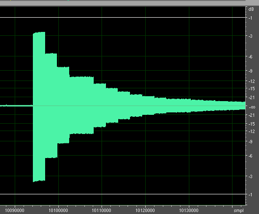
I think it's important to show how the contents of these two internal tables can be determined by measuring the external output of the YM2612, so allow me to show you a screencap:
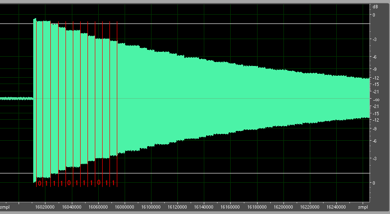
You can clearly see the steps in the attenuation here, including the pattern of cycles where the attenuation is and is not modified. This wave was created in SSG-EG mode, so the changes in amplitude are larger than normal (more on that later), but you can observe the same effect without SSG-EG active. This particular wave was produced with a calculated rate value of 7. Looking at the table above, that gives it an update cycle pattern of 0,1,1,1,0,1,1,1. You can see that pattern coming through in the output. The counter shift values increase the length between the steps.
This waveform also demonstrates the fact that the update cycle is based on a global clock. You can see at the start of this wave that there is a short period where the wave is held at 0db, before the first drop occurs. This drop does not occur at the same spacing as the rest of the changes that follow it. This demonstrates that each operator doesn't have its own running cycle counter. When you key-on an operator on the real system, it's possible for it to start at any point in the 8-cycle pattern of steps, and regardless of how large the spacing between steps, the first change in attenuation may happen at any time from the moment the note is keyed on, depending on what the global counter was up to when key-on occurred.
YM2612: Updating and outputting attenuation values
In the previous section, some pseudocode was presented showing the update cycle for attenuation values in the envelope generator. The part on actually adjusting the attenuation was left out. The update process is different between attack and decay. The decay phase is simpler, so I'll present that one first.
The decay phase:
Code: Select all
operator.attenuation += attenuationIncrement
The decay phase is a simple linear progression. You add the increment value to the attenuation on each update.
The attack phase:
Code: Select all
operator.attenuation += attenuationIncrement * (((1024 - operator.attenuation) / 16) + 1)
The attack phase is a little more complex. The attack phase produces an inverted exponential curve in attenuation, from maximum to minimum. This formula was derived after a little experimentation. This formula is only half the implementation however. In an earlier section, I mentioned that the envelope generator stores a flag for each operator indicating whether the output is inverted. During the attack phase, this flag is set. This effectively does a binary not of the attenuation when it is output, so 0x000 becomes 0xFFF, 0x12F becomes 0xED0, etc.
For the output of attenuation values, here's the basic process:
-Take a copy of the current internal 10-bit attenuation number
-If the output invert flag is set, perform a binary NOT on the number
-Add TL to the number. TL is converted to a 10-bit attenuation value first. A limit is applied to prevent the result from overflowing.
YM2612: The ASDR envelope
This is a quick summary of how the envelope generator manages the ASDR envelope.
1. Key-on occurs.
-The envelope generator sets the operator to the attack phase
-The rate parameter for the attack phase is calculated
-The current attenuation value is cleared
-The inverted output flag is set
2. The attenuation is continually adjusted, until attenuation reaches 0
-The envelope generator switches the operator to the decay phase
-The rate parameter for the decay phase is calculated
3. The attenuation is continually adjusted, until the attenuation value reaches SL
-The envelope generator switches the operator to the sustain phase
-The rate parameter for the sustain phase is calculated
4. The attenuation is continually adjusted until it hits max
At any point, key-off may occur. If it does, the following immediately occurs.
-The envelope generator sets the operator to the release phase
-The rate parameter for the release phase is calculated
-The inverted output flag is cleared
YM2612: SSG-EG mode
Ahh yes, now we've reached that part that every emulator gets wrong: SSG-EG mode. Well, right into it. The key feature SSG-EG provides is the ability to repeat the decay and sustain phases of the ASDR envelope over and over again. First of all, here's the SSG-EG register, as it's presented in the YM2608 documentation:
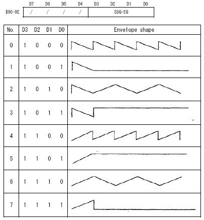
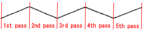
You'll see there are 8 patterns presented here, but there isn't any real indication given in the documentation of what these patterns mean, or how they affect the output waveform. What these patterns actually represent is a series of repetitions of the decay and sustain phases of the ASDR envelope, like so:
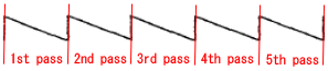
When the attenuation for the operator hits max, the envelope switches back to the attack phase. If you've got the attack rate set to 0x1F like the Yamaha documentation says you need to, you can effectively say the attenuation is reset to 0, and the envelope mode switches back to the decay phase. The next section will cover the interaction of SSG-EG with the attack phase.
Each repetition within these patterns is selected from one of 4 basic modes. These modes affect the way the decay and sustain phases proceed. Each mode shows how the amplitude changes in the decay phase over time. Here are what each of the 4 modes do:
1. Normal

This mode represents the normal progression of the decay and sustain phases. The amplitude starts at the maximum level, and proceeds to the minimum level, or in other words, the attenuation increases from 0 to max. This is the way the decay and sustain phases would proceed without SSG-EG mode active.
2. Inverted

The inverted output flag is set for the operator during this repetition. The calculation remains the same, but due to the inverted output, the 10-bit attenuation value will proceed from maximum to minimum, or in other words, rather than "decaying", the output will be increasing in volume.
3. Held

The output is simply held at maximum attenuation (minimum volume).
4. Inverted Held

An inverted version of the above. The output is held at minimum attenuation (maximum volume).
There's a better description of the 4 bits that set the SSG-EG mode than the one provided in the YM2608 manual.
Code: Select all
SSG-EG: $90-$9E
---------------------------------
| 7 | 6 | 5 | 4 | 3 | 2 | 1 | 0 |
|---------------|---|---|---|---|
| /   /   /   / | E |ATT|ALT|HLD|
---------------------------------
E = Enable. Unless this bit is set, SSG-EG mode is inactive, and none of the other bits have any effect.
ATT = Attack. When this bit is set, the inverted output flag is initially set at the start of the first decay phase.
ALT = Alternate. The inverted output flag is toggled after each repetition, alternating between 1 and 0.
HLD = Hold. After the decay and sustain phases have completed one full pass, the output is held at the final level. Once hold mode begins, it doesn't end until key-off.
If you look at the 8 patterns shown above, you'll see how these bits combine to create the patterns. Note that when you combine the ALT bit with hold, the inverted output flag is toggled before hold mode begins.
There is a second effect that SSG-EG has on all envelope generator decay phases, including the release phase. When an SSG-EG mode is applied to an operator, each time the attenuation value is being updated, the increase is multiplied by a factor of 6. Note that the envelope generator does not update any quicker in SSG-EG mode. The update cycles remain the same, but the amount that is added to the attenuation value is increased by a factor of 6 in the YM2612.
So, for the sake of completeness, as per the update formulae for the attack and decay phases given above, the following is the update formula for all decay phases under SSG-EG mode.
Code: Select all
operator.attenuation += 6 * attenuationIncrement
Note that the rate of change for the attack phase is not affected by SSG-EG mode, so the calculation previously given for the attack phase still stands. There are however a lot of other quirks to mention regarding the attack phase and SSG-EG mode. The interaction of the attack phase and SSG-EG is the topic of the next section.
YM2612: SSG-EG and the Attack Phase
Officially, Yamaha say the attack rate must be set to 0x1F in order to use SSG-EG mode. You can consider all behaviour of the YM2612 to be officially undefined and unsupported when you combine SSG-EG mode with an attack rate less than 0x1F.
The effect of having an attack value less than 0x1F with SSG-EG enabled is that the attack phase will also be included in each repetition of the envelope. SSG-EG does a loop of the attack, decay, and sustain phases. Although the rate of change in the decay phases are increased by a factor of 6 when SSG-EG is applied, the rate of change for the attack phase is unaffected, and is evaluated in its normal fashion. Each repetition of the envelope triggered by SSG-EG will repeat the attack, decay, and sustain modes.
The reason Yamaha say not to use the attack phase when SSG-EG is enabled, is because it really does mess things up. There are two issues it creates. The first issue relates to the nature of the calculation being performed to create the attack phase. The attack phase is an inverted exponential curve. The attenuation starts at maximum, and advances very quickly at first, but gradually slows as it approaches minimum attenuation. SSG-EG allows the output to be inverted. This doesn't change the actual calculation that is being performed in order to calculate the attack curve however, it literally just inverts the bits being output. This creates an attack curve which makes several extremely large, obvious steps from 0db, which are the most audible changes, while all the slower gradual changes occur at the other end of the scale, where the change in attenuation is much less noticeable. Here's a screenshot of what you get with an inverted attack curve:
The second issue with combining an attack phase with SSG-EG mode is a little more subtle, and a lot more serious. If you look in an earlier section where I present pseudocode for the update process for the attack phase, you'll see that I mention the attack phase uses the output inversion bit to invert the output. Both the decay and attack phases use an incrementing value to represent the attenuation value, but the attack phase uses this output inversion setting to negate the output, which creates a falling attenuation (rising volume), instead of a rising attenuation (falling volume). The problem is, SSG-EG mode uses the output inversion bit too, and they end up interfering with each other. Sometimes the beginning of the attack phase will override the changes made by SSG-EG mode, and sometimes it will be the other way around. The worst thing is, because the update timing of the attack cycle, like all envelope update cycles, is tied to the global cycle count for the envelope generator, the results are inconsistent. If you repeat a key-on for the operator without changing any settings, you might get quite a different result.
With a real attack phase and SSG-EG mode both active, the first two SSG-EG patterns always work correctly, as they don't affect the output inversion bit. Patterns which use the ATT bit to start the output inverted sometimes have their inversion overridden by the attack phase, so they will start non-inverted. Patterns which use the ALT bit are severely affected, as at the start of each repetition, including the first, there's a chance that it could go either way, so each successive repetition may either be inverted or not inverted. There's also often a cross-over period of one update cycle for the envelope phase, where the output inversion bit is set by SSG-EG, then overridden by the attack phase, creating a loud spike between each repetition.
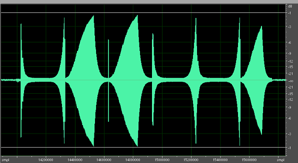
Here's a screenshot showing the messed up stuff you can get with the ALT bit set:
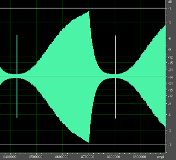
And here's a screenshot showing the noise spike you get between each cycle even when it behaves:
Emulating all these quirks would require exact knowledge of when these flags are set and cleared. I may do more work in this area at a later date.
YM2612: Current emulator support for SSG-EG mode
I haven't checked what emulators do about emulating SSG-EG mode with an attack phase, but here are some notes about current emulator support for SSG-EG mode in the YM2612.
-MAME doesn't clear the inverted output flag on release, so release during an inverted output creates a constant tone. MAME also only multiplies the attenuation increase by a factor of 4 in the decay and sustain phases, not 6. Interestingly, MAME also does not adjust the rate of the release phase, which it should.
-Kega doesn't do the release phase at all when SSG-EG is active, and messes up held notes. It does get the timing of the decay phase almost perfect however.
-Gens doesn't clear the inverted output flag on release, so it has a constant tone problem like MAME does. Gens doesn't seem to increase the decay phase increment at all, so each repetition of the decay phase runs 6 times too slow.
YM2612: SSG-EG Test ROM
Finally, here's a quick test rom which uses all 8 SSG-EG patterns:
http://nemesis.hacking-cult.org/MegaDri ... ssg-eg.bin
Here's the source:
http://nemesis.hacking-cult.org/MegaDri ... ssg-eg.asm
And here's a sample of the output you get on a PAL MD1600 MegaDrive, recorded at 96KHz:
http://nemesis.hacking-cult.org/MegaDri ... md1600.rar
And on that note, I'm going to get some sleep.

