VDP registers timings
Moderators: BigEvilCorporation, Mask of Destiny
VDP registers timings
Does someone know what happen if display is disabled during line scanning period (clearing VDP register 01 bit 6) ?
Is the current displayed line blanked or does this register setting won't apply until next scanline ?
Another question would be: for a given H interrupt, occuring after line N rendering has been finished, is this possible to modify some VDP settings during the interrupt routine so that the modification are taken in account while rendering line N+1 ? Or is it only possible to change settings for line N+2 (as stated in the manual) ?
From my tests... You can disable anytime the rendering (not the vdp)... the Hsync/Vsync will continue to work and the TV wont loose sync. When rendering is turned off, you get the DMA power of VBLANK.Does someone know what happen if display is disabled during line scanning period (clearing VDP register 01 bit 6) ?
Since (I think its Stef or TascoDlX who said that) the VBLANK period is 1/6 VBUSY+VBLANK periods... And since you can DMAte more tiles during VBLANK than during VBUSY, I let you guess power you get by extending the VBLANK period, even few pixels
*disable display
move.w #0x8134,0xc00004
*Enable display
move.w #0x8174,0xc00004
"Is the current displayed line blanked or does this register setting won't apply until next scanline ?"
If you do that when the line started (out of Hblank), the current line is drawn... If you do that during Hblank, the next line should not be drawn.
True. It is N+1. They may have written that in the doc because the HINT frequency is set (by default) to 2 lines... But you can set it to one line.modify some VDP settings during the interrupt routine so that the modification are taken in account while rendering line N+1 ?
I can't confirm... But in few demos, raster effects applies on each line without problem. Maybe some vdp regs takes 2 lines to refresh? No idea, sorry.
Also, I noticed that the sega nomad react a bit differently on HINT... I don't remember precisely, but I think there is a little timing glitch on this hardware.
Good luck!
(PS: please refer to the segacd thread "software 3d rendering".. There is a short introduction to the DMA boosting trick, if you want
Bye
Fonz
-
TmEE co.(TM)
- Very interested
- Posts: 2452
- Joined: Tue Dec 05, 2006 1:37 pm
- Location: Estonia, Rapla City
- Contact:
Hmm, I'm getting my hands on a Nomad for a limited time this week... I could check something on it...
Mida sa loed ? Nagunii aru ei saa 
http://www.tmeeco.eu
Files of all broken links and images of mine are found here : http://www.tmeeco.eu/FileDen
http://www.tmeeco.eu
Files of all broken links and images of mine are found here : http://www.tmeeco.eu/FileDen
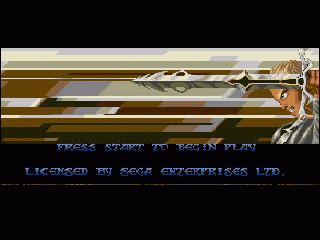
In fact, the question came from disassembling the game "Legend of Galahad" because I noticed a single line glitch on emulator when playing the intro

Here, HINT is set to occur at line 176 (and by this I mean AFTER line 175 has been scanned) and the first instruction of the HINT routine is indeed move.w #0x8134,0xc00004, which, as you said, disable display.
If I render line 176 BEFORE executing this instruction, line 176 is glitchy... But if I execute one single HINT instruction and then render the line, the glitch is gone. That's why I presume this line is supposed to be blanked.
The fact is that too many other games do not work properly if we execute even only one Hint cycle before rendering the line at which Hint occured, so maybe it has to do with some very tight timings:

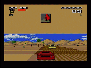
In this game for example, the Hint routine occurs at every line and the first instruction is a MOVE.L (a5)+ (a6) , which writes 2 new data words into VSRAM. The sky in the upper part disappears if we execute this single instruction before rendering the according line.
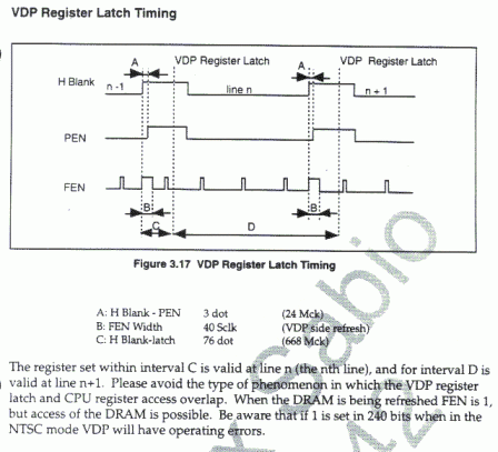
Now, according to the Sega manual, when Hint start, the VDP need 36 cycles to fetch all "required" VDP informations for rendering the upcoming line, so maybe this is enough for writing to one VDP register but really nothing else ?

Here, HINT is set to occur at line 176 (and by this I mean AFTER line 175 has been scanned) and the first instruction of the HINT routine is indeed move.w #0x8134,0xc00004, which, as you said, disable display.
If I render line 176 BEFORE executing this instruction, line 176 is glitchy... But if I execute one single HINT instruction and then render the line, the glitch is gone. That's why I presume this line is supposed to be blanked.
The fact is that too many other games do not work properly if we execute even only one Hint cycle before rendering the line at which Hint occured, so maybe it has to do with some very tight timings:

In this game for example, the Hint routine occurs at every line and the first instruction is a MOVE.L (a5)+ (a6) , which writes 2 new data words into VSRAM. The sky in the upper part disappears if we execute this single instruction before rendering the according line.
Now, according to the Sega manual, when Hint start, the VDP need 36 cycles to fetch all "required" VDP informations for rendering the upcoming line, so maybe this is enough for writing to one VDP register but really nothing else ?
I know that at least you can change the backdrop register ($07) anytime during a line, and it takes effect immediately. Unless you can get a stable raster (as it's called on the C64), this is not really useful for anything without sprite masking at the split. I'm not even sure how you'd get a stable raster on the Genesis, although I'm sure it's possible. No emulator that I know of currently supports mid-line backdrop changes, but I know for a fact it works on hardware, I used to have a little proof-of-concept thing that I wrote ages ago (and lost in a hard drive crash) and it ran fine on both my systems.
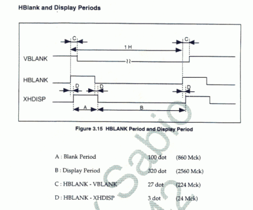
I found this in 32x docs (always nice to learn new things  )
)


I guess the same thing could also apply to the Genesis VDP (they use the same clock I think)
note that it seems some values are wrong: how can 76 pixels correspond to 668 MClk when the pixel clock is usually Mclk/8 (confirmed by the other values)


I guess the same thing could also apply to the Genesis VDP (they use the same clock I think)
note that it seems some values are wrong: how can 76 pixels correspond to 668 MClk when the pixel clock is usually Mclk/8 (confirmed by the other values)
-
Chilly Willy
- Very interested
- Posts: 2993
- Joined: Fri Aug 17, 2007 9:33 pm
I assume it was either an error in the original docs, or an OCR error when someone converted the original docs. Look where it says 100 dots -> 860 mclks. Possibly an OCR error converting a 0 into a 6. That's the same error you see in the 76 -> 668. It should be 608, so I'd guess yet another 0 converted into a 6 OCR error.Eke wrote:I found this in 32x docs (always nice to learn new things)
I guess the same thing could also apply to the Genesis VDP (they use the same clock I think)
note that it seems some values are wrong: how can 76 pixels correspond to 668 MClk when the pixel clock is usually Mclk/8 (confirmed by the other values)
-
evildragon
- Very interested
- Posts: 326
- Joined: Mon Mar 12, 2007 1:53 am
- Contact:
yes, strange coincidenceChilly Willy wrote: I assume it was either an error in the original docs, or an OCR error when someone converted the original docs. Look where it says 100 dots -> 860 mclks. Possibly an OCR error converting a 0 into a 6. That's the same error you see in the 76 -> 668. It should be 608, so I'd guess yet another 0 converted into a 6 OCR error.
but then why 27 dots = 224 MCK ?
I think these are errors from the original doc
860 MCk for HBLANK seems right because 860+2560 = 3420 = 10 x 342 dots (remember that the dot clock in H32 mode is MCLK/10 and that a full line is approx. 342 pixels)
That's why I assumed that the cycles count were right and that dot counts were only approximation with some errors
-
Chilly Willy
- Very interested
- Posts: 2993
- Joined: Fri Aug 17, 2007 9:33 pm
Maybe. There were bulletins for the 32X as well. Maybe one of them has an errata for the manual.Eke wrote:yes, strange coincidenceChilly Willy wrote: I assume it was either an error in the original docs, or an OCR error when someone converted the original docs. Look where it says 100 dots -> 860 mclks. Possibly an OCR error converting a 0 into a 6. That's the same error you see in the 76 -> 668. It should be 608, so I'd guess yet another 0 converted into a 6 OCR error.
but then why 27 dots = 224 MCK ?
I think these are errors from the original doc
860 MCk for HBLANK seems right because 860+2560 = 3420 = 10 x 342 dots (remember that the dot clock in H32 mode is MCLK/10 and that a full line is approx. 342 pixels)
That's why I assumed that the cycles count were right and that dot counts were only approximation with some errors
I have another question, this time related to V-RAM accesses:
what happen if you are writing to CRAM/CVRAM/VSRAM during HDISPLAY ?
does the VDP take the new values in account when rendering the last pixels (or most probably, groups of pixels), resulting in some mid-line changes or are all needed values fetched during HBLANK ?
what happen if you are writing to CRAM/CVRAM/VSRAM during HDISPLAY ?
does the VDP take the new values in account when rendering the last pixels (or most probably, groups of pixels), resulting in some mid-line changes or are all needed values fetched during HBLANK ?
-
TmEE co.(TM)
- Very interested
- Posts: 2452
- Joined: Tue Dec 05, 2006 1:37 pm
- Location: Estonia, Rapla City
- Contact:
Writing to CRAM during frame will cause some colored dots appear... I have no idea what happens when other things are written to.
Mida sa loed ? Nagunii aru ei saa 
http://www.tmeeco.eu
Files of all broken links and images of mine are found here : http://www.tmeeco.eu/FileDen
http://www.tmeeco.eu
Files of all broken links and images of mine are found here : http://www.tmeeco.eu/FileDen
I noticed the dots were made of first color of first palette loaded in CRAM 
So you can eventually reduce the "impact" of those by setting this first CRAM entry with the color of your choice
You can also select a different color for screen borders by picking it in another palette.
Its just a notice I made some years ago, please do your own checks
So you can eventually reduce the "impact" of those by setting this first CRAM entry with the color of your choice
You can also select a different color for screen borders by picking it in another palette.
Its just a notice I made some years ago, please do your own checks
Actually, the dots that appear are the colour of the value you write. Essentially, when you write to CRAM, the single pixel that is being drawn at that moment displays the colour you were writing to the CRAM at that moment, regardless of the colour that should have been displayed. This occurs even when the display is disabled, or when the VDP is rendering the screen boarders, and one write always changes the colour of a single pixel if the VDP is in the process of rasterizing a line.
I've done extensive testing on this behaviour. You can actually use it to measure the timing of the FIFO buffer during active scan, as it allows you to see visually on the screen when each CRAM write gets through. I've emulated mid-line writes to CRAM, as well as this flicker bug, in my emulator. As for other settings though, like when specific register changes take effect, I haven't sampled that information yet. I'm planning to test each and every register setting, and writes to all the various buffers in ram to determine when the VDP samples all its data, and compile the results into a single document. It's essential in order to get the VDP emulation "perfect", and avoid all potential single-line raster problems like the one in Galahad, so I'll definitely be doing it at some point.
I may as well add a bit more info, I've noticed from observing the FIFO timing that there are a series of "slots" in fixed positions for each scanline when buffered writes go through. I'll be calculating the precise coordinates for those quite soon, but they appear to be 2 cells apart starting from the left side of the screen. There was also one mark in an odd position near the end of each line, which I believe corresponds with the position where the HINT is triggered.
There are a number of factors that lead me to believe that the VDP renders the screen in 2-cell segments internally, and it is logical that the only time data can be changed and produce predictable results is at the end of each of these 2 cell blocks, which the FIFO enforces. I suspect changes to ram are seen at the end of each of these blocks, but there are some questionable values, like hscroll data which I'd have to test to be sure, and I very much doubt mid-line changes to the sprite table are seen. As for register changes, I suspect these are only applied at some point during hblank. Again, this needs testing though.
Last edited by Nemesis on Mon May 19, 2008 12:57 am, edited 1 time in total.
Oh, just to confirm, after thorough testing, the only kind of access to the VDP which causes these kind of glitches that I've observed are writes to CRAM. Registers, VRAM, and VSRAM had no observable effect. As I'm typing this though, I can't recall if I did a complete set of tests with reading data. I know I tested reading CRAM data however, and that did not cause any visual glitches.TmEE co.(TM) wrote:Writing to CRAM during frame will cause some colored dots appear... I have no idea what happens when other things are written to.