VDP Internals

For anything related to VDP (plane, color, sprite, tiles)

Moderators: BigEvilCorporation, Mask of Destiny

Charles MacDonald
Very interested
Posts: 292
Joined: Sat Apr 21, 2007 1:14 am

Post by Charles MacDonald » Sat Feb 16, 2013 2:13 am

Chilly Willy wrote:That's still 234 lines on NTSC... I'd probably just go one more cell for 232 lines. I'd combine functions and not just switch modes, but then jump to the vblank code. No need to even have a vblank interrupt.
Oh just to be clear you can't extend the screen area by switching into V30 mode and back. You can on the SMS 2, but it doesn't work the same way on the Genesis. I tried it, and Nemesis was correct, it doesn't work.

On the flip side you can shrink the screen by going into mode 4 and back, but that's not exactly what people want. :D

Slightly OT but I tried that DMA color trick with some taller images with interlacing on and it looks pretty good. Having the high vertical resolution of interlace mode makes up for the lack of horizontal resolution. On my CRT the visible area was about 158x416 which isn't too bad.

Chilly Willy
Very interested
Posts: 2984
Joined: Fri Aug 17, 2007 9:33 pm

Post by Chilly Willy » Sat Feb 16, 2013 3:59 am

Oh well, too bad about the extended height problem, but kudos for the interlaced direct color mode! :D

Eke
Very interested
Posts: 885
Joined: Wed Feb 28, 2007 2:57 pm
Contact:

Post by Eke » Thu Apr 18, 2013 12:01 am

Mask of Destiny wrote:
!HSYNC is low for exactly half the number of ticks of SC (so 32 for 40-cell and 26 for 32-cell) for some portion of the inactive display period. This starts 10th pulse of !HSYNC after the begin of the inactive display period and it goes back to normal on the 7th !HSYNC pulse after !VSYNC goes high again. Stated another way, there are 8 short !HSYNC pulses before !VSYNC goes low and 6 short !HSYNC pulses after !VSYNC goes high. All of the six of the !HSYNC pulses that occur while !VSYNC is low are short. The time betweein !HSYNC pulses is also cut in half.
.
I had a question about this: does that mean that there are 20 lines (if i've counted right ?) during VBLANK that are actually shorter, i.e the number of cycles between two VCounter increments is actually not 3420 but 1710 MCLKS ? And, by extension, that the number of cycles per frame (i.e between two VBLANK interrupts) is not exactly 262x3420 MCLKS but slightly less ? This would actually explain some CPU benchmarks differences I observed between emulators & real hardware.

Wouldn't it also affect external access slots during these lines and therefore reducing the effective number of slots available during VBLANK ?

Lastly, apart from timing differences, I am also curious how HCounter range is affected on these specific lines

Mask of Destiny
Very interested
Posts: 624
Joined: Thu Nov 30, 2006 6:30 am

Post by Mask of Destiny » Thu Apr 18, 2013 12:40 am

So after reading up a bit more on television signals it's pretty clear that these have to do with the equalizing and vertical sync pulses. In standard NTSC there are 9-9.5 lines that have twice as many sync pulses as normal lines. 3 lines of pre-equalization pulses, 3 lines of vertical sync pulses and 3-3.5 lines of post-equalization pulses (3 for an odd frame, 3.5 for an even frame). So this isn't actually 20 lines, it's just 10 lines with twice as many HSYNC pulses. Not sure why there's an extra line in there. It's possible I counted wrong when looking at the captured data, but it's also possible that the signal is a bit non-standard (most TVs are relatively forgiving). So my guess is that this would have no impact on the HV counter or number of access slots.

One thing that does impact the number of access slots is that due to the way sprites are rendered the VDP effectively renders 225 lines, not 224.

Mask of Destiny
Very interested
Posts: 624
Joined: Thu Nov 30, 2006 6:30 am

Post by Mask of Destiny » Wed Sep 04, 2013 7:07 am

I have a couple of small tidbits that I discovered since I last posted in this thread. First is VRAM refresh behavior when the display is off (either during VBLANK or when you disable it). You would think that the refresh slots would be in exactly the same place as when the display is enabled, but that's not the case. In fact, the number of refresh slots per line is not the same either.

In H40 mode, there are 6 refresh slots when the display is off. There is one refresh slot every 32 slots starting at slot 37 (assuming slot 0 = the first slot in which sprite tile data is read). The refresh slots are: 37, 69, 102, 133, 165 and 197. This means that contrary to the documentation, the 68K->VRAM DMA capacity is only 204 bytes rather than 205.

In H32 mode there are 5 refresh slots when the display is off as opposed to 4 when the display is on. I haven't gotten around to determining exactly which slots they are though.

I can also confirm that 68K->VDP DMA transfers go through the FIFO. This means that if a transfer is small enough to fit in the FIFO, the bus can be returned to the 68K before the data is written to the destination. The DMA engine will perform one read per slot until the FIFO is full. When a refresh slot occurs, you lose a single write slot, but you actually lose 2 68K read slots. When VRAM is the destination, this doesn't really matter since each word read needs 2 slots to write to VRAM; however, for VSRAM and CRAM you lose an extra transfer for each refresh slot. This gives you only 198 transfers per line in H40 mode.

If you look very closely at the direct color DMA demos you can actually see this in action. You'll see one double pixel where the write is blocked by refresh and then you'll see a second one 3-pixels later. Presumably, the delay is caused by FIFO interaction, but I haven't quite worked out the exact mechanics of that.

Chilly Willy
Very interested
Posts: 2984
Joined: Fri Aug 17, 2007 9:33 pm

Post by Chilly Willy » Wed Sep 04, 2013 5:26 pm

Mask of Destiny wrote:If you look very closely at the direct color DMA demos you can actually see this in action. You'll see one double pixel where the write is blocked by refresh and then you'll see a second one 3-pixels later. Presumably, the delay is caused by FIFO interaction, but I haven't quite worked out the exact mechanics of that.
Yeah, the DMA Direct Color mode is an excellent way to explore the effect and timing of refresh cycles. Hmmm, that gets me to thinking - do any of the extra control/test registers affect the refresh? Starting a DDC display while checking the extra bits might help detect any changes to refresh by the registers.

Charles MacDonald
Very interested
Posts: 292
Joined: Sat Apr 21, 2007 1:14 am

Post by Charles MacDonald » Thu Sep 05, 2013 8:51 pm

Hmmm, that gets me to thinking - do any of the extra control/test registers affect the refresh? Starting a DDC display while checking the extra bits might help detect any changes to refresh by the registers.
I tried, this, none of the bits do anything except for for:

Bit 1, which when set fills the screen with repeating garbage and the machine seems to halt. Maybe it prevents the DMA from completing. The reset button does nothing and you have to cycle power. The data shown doesn't look like anything from the data being transferred by DMA.

Bit 8 makes some dark colored pixels appear, but it doesn't change anything about the refresh.

Mask of Destiny
Very interested
Posts: 624
Joined: Thu Nov 30, 2006 6:30 am

Post by Mask of Destiny » Tue Sep 10, 2013 6:55 pm

So I now understand the mechanism behind the 3-pixel delay between the doubled-pixels in the direct color DMA demo. It turns out there's something like a 3-slot latency on data going through the FIFO. So even if the FIFO is empty, it takes 2-3 slots (depending on how exactly you measure) for data to hit the destination. As a result, the FIFO has 3 words in it when the first double pixel is displayed, those get emptied over the next 3 slots following refresh, but only the last 2 of those slots have a read from the 68K bus. By the second doubled-pixel there are actually 2-words in the FIFO, but due to the latency involved they're not actually available to be written yet.

Other random stuff:
DMA fill is kind of strange and it seems like Exodus is the only emulator that gets it remotely correct (well I didn't check Gens, but at least Fusion 3.63 and my few month-old checkout of Genesis Plus GX don't handle it correctly). The data word write that actually kicks off the fill actually gets written normally and does not count against the DMA length. The MSB of that word is then used for the fill. If another data-port write is done before the fill is finished, that write will occur as normal (might get doubled in some circumstances, need to double-check the results on hardware vs what the demo code is doing) and the MSB of that new word will be used for the remainder of the fill.

It seems there's some weird interaction between register 0x17 (DMA source high) and CD/command words. Setting 0x17 seems to corrupt whatever is in CD. If you setup VRAM writes and then set reg 0x17 to say 0, subsequent writes to the data port will behave as if they're going to a word-wide RAM in that it only takes a single slot for a FIFO-entry to clear rather than two. I haven't yet investigated where they are actually going (assuming they're going anywhere at all).

If you instead reverse the order and set reg 0x17 and then try to setup non-DMA writes to VRAM, the system will lock up as the second-word of the command word is written.

Both behaviors occur even if DMA is disabled.

Eke
Very interested
Posts: 885
Joined: Wed Feb 28, 2007 2:57 pm
Contact:

Post by Eke » Tue Sep 10, 2013 8:35 pm

Mask of Destiny wrote:The data word write that actually kicks off the fill actually gets written normally and does not count against the DMA length. The MSB of that word is then used for the fill.
Hum, that is actually how it is emulated in Genesis Plus GX, I remember doing some tests since it was not very clearly answered (I think there is some thread about it somewhere on that board). Note that this means the official doc, which says the max transfer per line for VRAM Fill is one byte less that the number of external access slots, is not entirely correct: it is actually two bytes less, considering the initial data port write takes two slots.
Mask of Destiny wrote:If another data-port write is done before the fill is finished, that write will occur as normal (might get doubled in some circumstances, need to double-check the results on hardware vs what the demo code is doing) and the MSB of that new word will be used for the remainder of the fill.
This I didn't know, CTRL and DATA port access during DMA was not recommended practice for games so it's indeed poorly emulated. Now it seems logical that the Fill operation is using the word in the FIFO as source data and that the Fifo is still accessible during DMA operation. I wonder if you can corrupt VRAM Copy the same way since we know VRAM read is using the FIFO as buffer. It probably requires thougher write timings to get in between the read and the write accesss.
Mask of Destiny wrote: It seems there's some weird interaction between register 0x17 (DMA source high) and CD/command words. Setting 0x17 seems to corrupt whatever is in CD. If you setup VRAM writes and then set reg 0x17 to say 0, subsequent writes to the data port will behave as if they're going to a word-wide RAM in that it only takes a single slot for a FIFO-entry to clear rather than two. I haven't yet investigated where they are actually going (assuming they're going anywhere at all).

If you instead reverse the order and set reg 0x17 and then try to setup non-DMA writes to VRAM, the system will lock up as the second-word of the command word is written.

Both behaviors occur even if DMA is disabled.
I think what causes this is bit7 in that register, I've seen a few homebrew that would hang on startup because that register was not initialized to $80 like with official startup code. I believe that clearing this bit actually does something to the 68k bus interface (it is normally cleared to indicate the DMA source is external) so that VDP can later becomes the master of the bus. Maybe it has some impact on the bus ctrl signals, which cause the data written to VDP ports to be mishandled.

Mask of Destiny
Very interested
Posts: 624
Joined: Thu Nov 30, 2006 6:30 am

Post by Mask of Destiny » Tue Sep 10, 2013 10:47 pm

Eke wrote: Hum, that is actually how it is emulated in Genesis Plus GX, I remember doing some tests since it was not very clearly answered (I think there is some thread about it somewhere on that board). Note that this means the official doc, which says the max transfer per line for VRAM Fill is one byte less that the number of external access slots, is not entirely correct: it is actually two bytes less, considering the initial data port write takes two slots.
Yeah, I believe that particular aspect seemed to work correctly in Genesis Plus-GX when I tested it, it was just the mid-fill writes that were not handled correctly so perhaps my language was a bit strong there. Fusion didn't seem to do either though. I'll post my test ROM and a screenshot once I've cleaned up the code for general consumption (it currently relies too much on the initialization done by the Mega Everdrive).
Eke wrote:I wonder if you can corrupt VRAM Copy the same way since we know VRAM read is using the FIFO as buffer. It probably requires thougher write timings to get in between the read and the write accesss.
I'm curious about that too. It's on my to-do list to test that.
Eke wrote:I think what causes this is bit7 in that register, I've seen a few homebrew that would hang on startup because that register was not initialized to $80 like with official startup code.
If you can think of any examples off-hand, I'd be interested to know which ones.
Eke wrote:I believe that clearing this bit actually does something to the 68k bus interface (it is normally cleared to indicate the DMA source is external) so that VDP can later becomes the master of the bus. Maybe it has some impact on the bus ctrl signals, which cause the data written to VDP ports to be mishandled.
Yeah that makes a certain amount of sense as setting the other two DMA source address registers is not a problem. I'll do some more tests when I get a chance to see if I can reproduce either symptom with bit 7 set.

Charles MacDonald
Very interested
Posts: 292
Joined: Sat Apr 21, 2007 1:14 am

Post by Charles MacDonald » Wed Sep 11, 2013 2:37 am

Yeah, I believe that particular aspect seemed to work correctly in Genesis Plus-GX when I tested it, it was just the mid-fill writes that were not handled correctly so perhaps my language was a bit strong there.
Are there any games that rely on accessing the data port during fill or copy operations?

My concern is that while the timing information we have nowadays can make such behavior repeatable, or even useful, I don't think the developers had that kind of timing data back then. So if a game uses it, it must be accidental rather than purposeful?

I guess it's like testing to see which emulators support the full-screen CRAM DMA display trick; most don't because no commercial games used it. ;)

Mask of Destiny
Very interested
Posts: 624
Joined: Thu Nov 30, 2006 6:30 am

Post by Mask of Destiny » Wed Sep 11, 2013 4:36 am

Charles MacDonald wrote:Are there any games that rely on accessing the data port during fill or copy operations?
I'm not aware of any game that does and it seems unlikely anyone would use it on purpose. It doesn't seem all that useful, though perhaps someone will come up with some crazy demo-scene trick that uses it somehow.
Charles MacDonald wrote:I guess it's like testing to see which emulators support the full-screen CRAM DMA display trick; most don't because no commercial games used it. ;)
Yeah, my intent is not so much to criticize these emulators and I apologize if I come off that way. Wanting to perfectly emulate the entire commercial library while not bothering with quirky details none of those games use is a reasonable goal, but for the sake of the demo scene and emulators that have different goals I think having this information is useful.

Eke
Very interested
Posts: 885
Joined: Wed Feb 28, 2007 2:57 pm
Contact:

Post by Eke » Wed Sep 11, 2013 6:54 am

Mask of Destiny wrote: If you can think of any examples off-hand, I'd be interested to know which ones.
i remember the port of Super Mario Bros being one of them

viewtopic.php?t=755&postdays=0&postorder=asc&start=15

I have the feeling this bit modifies something regarding the VDP 68k bus and DMA interfaces (maybe FIFO as well). We know that the VDP generates a few signals for the bus during normal operation ( CAS0, RAS0, DTACK) and that DMA operates faster than the 68k cpu when master of the bus, so maybe the timing of some signal changes. It might as well explain why setting up the dma using code running from ROM was not recommanded. It would also be interesting to test if behavior is the same on different revision of the VDP

Nemesis
Very interested
Posts: 791
Joined: Wed Nov 07, 2007 1:09 am
Location: Sydney, Australia

Post by Nemesis » Wed Sep 11, 2013 1:28 pm

I wasn't planning on posting this until it was a lot more cleaned up, but I can see there's a lot of interest in this area right now, and I'm very short on time, so here you go:
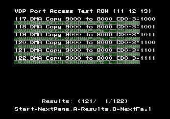
Image
http://nemesis.hacking-cult.org/MegaDri ... esting.zip

Consider this an alpha version. This increasingly misnamed test ROM contains over 100 VDP test suites, each of them usually containing half a dozen or more tests, which verify many, many points of VDP behaviour surrounding port access. The goal is for it to test for every kind of behaviour which can be observed through VDP port access. This means it has no pure rendering tests, but it has many many other tests which involve how the VDP processes commands, and what information it returns, under all kinds of crazy corner cases.

I used this ROM as my primary code-based testing platform for VDP port access testing while developing my emulator Exodus, and I rely on it heavily as a regression tester for my emulator. There are still a bunch more tests I want to add to this ROM, in particular it needs some tests surrounding the HV counter, but it does a lot as it stands. There are a lot of completely undocumented things this test ROM demonstrates the behaviour of, including crazy things like port writes during DMA fill operations.

What I want from this ROM in the end is to have every test nicely documented, and all the expected results explained, so someone can go through the tests and understand how to design a VDP core so it can pass every test. That hasn't happened yet. Expect a lot of incorrect nonsense and guesswork written down inside the notes within each test. In fact, a lot of the tests will have incorrect information. Sometimes I designed a test to prove something worked a certain way, and ended up discovering that it didn't, so some comments may actually indicate the reverse of the true result. Unfortunately, the final correct comments usually only ended up as source comments within my VDP core, so until I manage to get Exodus ready for its source release, the documentation to describe why certain tests produce the results they do are somewhat lacking. The test results themselves however are valid, and they all pass on the hardware, with a few exceptions:
1. The Genesis 3 fails quite a few tests, as it actually has an 0x80 byte VSRAM, not a 0x50 byte VSRAM like earlier VDP models.
2. The three tests which perform data port writes during a DMA fill operation fail occasionally. I'm working on making these 100% stable.
3. The DMA Fill FIFO usage test gets the first write byte order reversed intermittently on the real hardware (and Exodus) due to timing sensitivity. This is an old test, I need to modify it to make it stable.

This test ROM was developed alongside my emulator, so it has a major home field advantage, but Exodus currently passes 121 of the 122 active test suites, the failing one of which is highly timing sensitive and I know is failing due to known timing errors in my M68000 core. For reference, Kega Fusion only passes 17, and other emulators like Gens and Regen are in a similar region. RetroCopy does pass the most of any other emulator out there, but it's still only somewhere in the 40's or 50's from memory. Note that there are a number of tests that cause current emulators to fail. Kega gets screen corruption partway through. Regen locks up on one test, and RetroCopy crashes on another. Look in the main source file for notes on which tests have issues. You can disable them if you want to do a build that'll work in those emulators.

Anyway, these tests should shed a lot of light on quite a few of the topics you're currently talking about. I'm happy to answer questions about any of these tests, or to describe the inner workings of specific parts of the VDP in greater detail, as much as I understand them at this point anyway.

Edit: The file I linked to was an old build that I remembered had a critical bug that prevented it working properly, so I've uploaded a new version with the error fixed. I've also added a screenshot and fact-checked the actual results from running this build.

Eke
Very interested
Posts: 885
Joined: Wed Feb 28, 2007 2:57 pm
Contact:

Post by Eke » Wed Sep 11, 2013 8:01 pm

Thank you for posting this, this must have been a tremendous work figuring and putting all these tests together. Anyway, even with limited documentation, it will surely help improving the accuracy of emulators... and help understand better how some stuff are working inside the VDP.

Here are the results I got with my current version of Genesis Plus GX, although there are a few tests failing (VDP RAM byteswapping, DMA source wrapping, DMA Copy length reg update, all DMA to VSRAM tests) that I thought it would handle just fine. I'm curious to see what odd case you actually tested , haven't got the time to look into the source notes yet 8)

Image


Regarding VRAM reads (discussed a little in thisthread), I've recently done some tests involving FIFO empty/full flags and HV counter (to check for delayed port access) and I figured that:

1) FIFO state has no impact on CTRL port writes: you can actually setup a READ operation while the FIFO is full and it still returns without delay => this means the VDP command list stores the source/destination as well as the type of access (presumably, setting a READ operation adds a read command at the end of the list)

2) FIFO state is only affected by WRITE operations: setting a READ operation does not clear the FIFO EMPTY flag and this flag isn't cleared either when the read data is available.

3) reading from DATA port hangs until read command has been processed (and data is available): if the FIFO is full when the read is being setup, the DATA port read will takes more time than if the FIFO was empty => this indicates the read command is processed after all writes have been processed and FIFO is empty.


Can you confirm these observations ?

Post Reply