YM2612/YM3438 are not the only chips which do time-multiplexing of the output channels rather than using a 'real' accumulator to mix them (the 3438 DOES use multiplexing, right?):
The YM2413 OPLL and the Konami VRC7 (which is a reduced-ym2413-on-a-famicom-mapper-chip, almost certainly manufactured by yamaha for konami) both do it too.
Other 'internal use only' chips such as the YM3427 (a vastly-reduced-pin-count SSG-plus-extras, possibly AY-3-8930 (yes, 8930, not 8910) compatible, chip used on the PSS-80 keyboard) may do so as well.
LN
New Documentation: An authoritative reference on the YM2612
Moderator: BigEvilCorporation
-
Lord Nightmare
- Interested
- Posts: 19
- Joined: Sun Oct 12, 2008 10:45 pm
I made some tests to get amplitude-frequency characteristic of console's sound and then I remember one strange thing (see below) and made one more test.
Here are sources and binaries (2.5 kb)
For getting AFC I firstly wrote demo ym_67.asm (octave 6, multiplier 7), which makes frequencies up to 23080 Hz, but AFC looked unnaturaly in 48 kHz oscillogram (because it can't handle 23 kHz sinus and more high frequencies absent), then I made ym_77.asm (octave 7, multiplier 7) - for 46161 Hz. This is 96 kHz oscillogram from my European MD1:
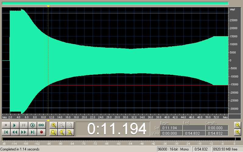
You can see that the more high frequency the more it's filtered. But that's not all.
Long ago I noticed that YM doesn't produce pure sinus, it produces multiple harmonics of it. If you play frequency F, you will also get frequencies 2F, 3F and so on. Maybe you noticed this fact too.
Also when I recorded tunes from HW at 96 kHz I noticed that the high part of spectrum (40+ kHz) is sort of mirror of its low part. It's not bug of my ADC because it records high freqs correctly (for example, 37 kHz from PSG).
Here's spectrogram of previous sweep:
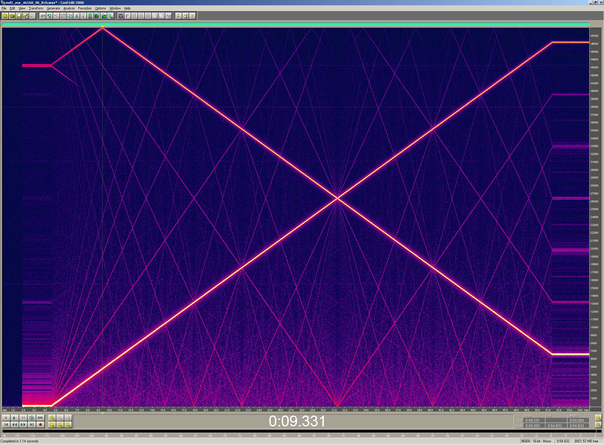
This is interesting sight
You see multiple harmonics of every frequencies (they look like the web) and you see freqs' reflection.
Our main harmonic and its reflection cross at point of 26390 Hz. On the left side at the top there is corner made by two lines. Its frequency is 48 kHz and its reflection is at 4780 Hz. And on the right side main harmonic is 46160 Hz (our program produced it) and its reflection is 6620 Hz.
If we sum main and "mirror" frequencies, we will get 52780 Hz - it's base frequency of YM.
To the left of that "corner" there is phantom of low frequencies. It starts from 43220 Hz, that is 96000 - 52780. I dunno what causes this phantom, but it's present.
This reflection certainly is not result of my ADC, you may see that after 26390 Hz (point of crossing) "main harmonic" become more weak than its reflection and sound sweeps to low freqs. It can be heard right in headphones.
So, for YM it doesn't matter, do you generate freq X or (MAX-X) (MAX = 52781 or 53267), result will be the same. At first pic you can see red line showing one volume level. At the right there is 46160 Hz (final freq of our program) and at the left is... 6620 Hz!
One more pic to show multiple harmonics:
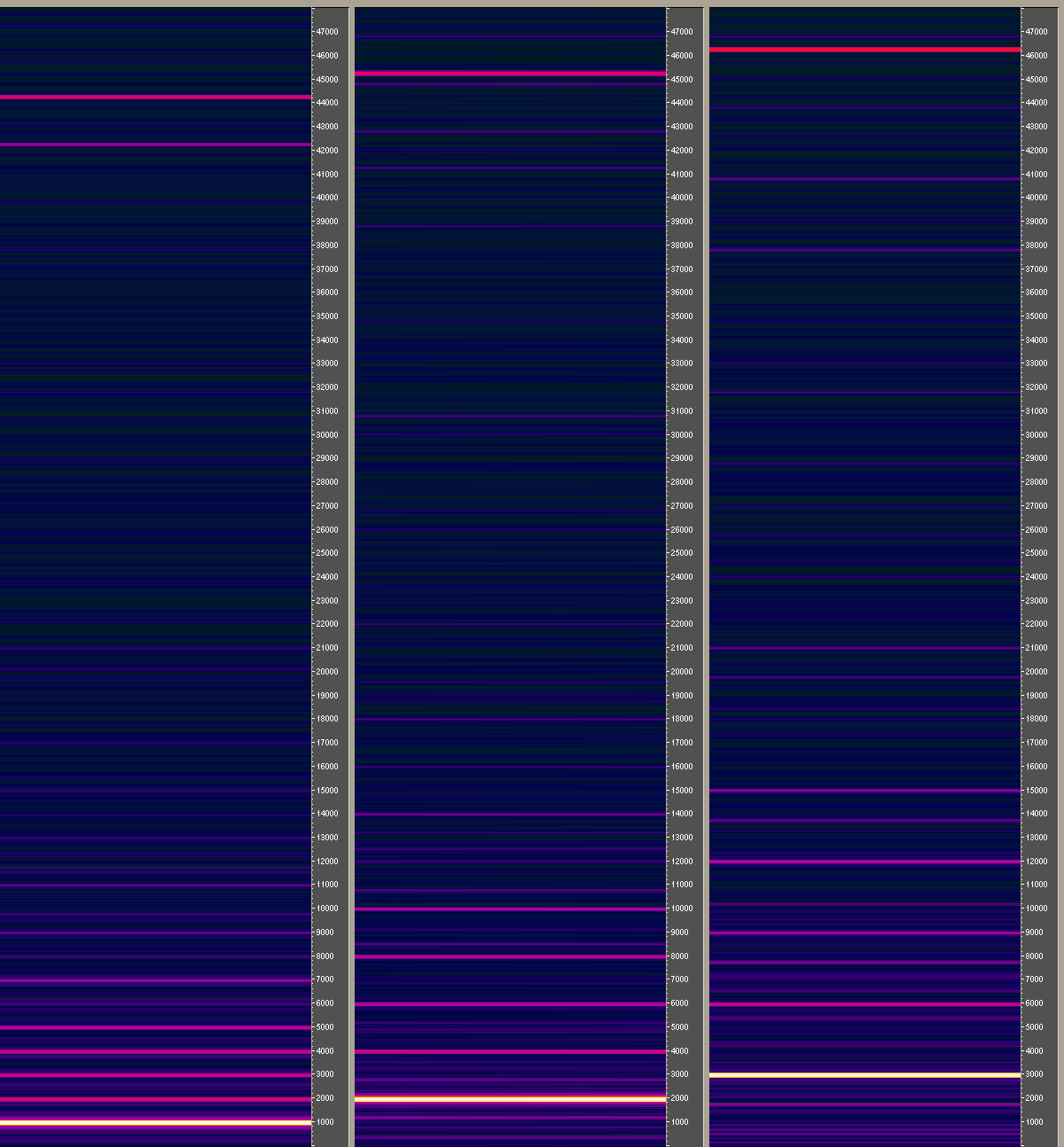
You see that after 5th repetition even harmonics are more weak than odd ones. And then, 13 is weaker than 11 and 15, 19 is weaker than 17 and 21 and so on. At the right side you may see 3 kHz and low reflections of its repetitions: 1780 (52780 - 3000*17), 7780, 13780, 19780...
Why YM can't generate pure sinus, what's the reason of multiple harmonics and what causes this reflection? Can anyone provide recording at 192+ kHz or its spectrogram?
Here are sources and binaries (2.5 kb)
For getting AFC I firstly wrote demo ym_67.asm (octave 6, multiplier 7), which makes frequencies up to 23080 Hz, but AFC looked unnaturaly in 48 kHz oscillogram (because it can't handle 23 kHz sinus and more high frequencies absent), then I made ym_77.asm (octave 7, multiplier 7) - for 46161 Hz. This is 96 kHz oscillogram from my European MD1:
You can see that the more high frequency the more it's filtered. But that's not all.
Long ago I noticed that YM doesn't produce pure sinus, it produces multiple harmonics of it. If you play frequency F, you will also get frequencies 2F, 3F and so on. Maybe you noticed this fact too.
Also when I recorded tunes from HW at 96 kHz I noticed that the high part of spectrum (40+ kHz) is sort of mirror of its low part. It's not bug of my ADC because it records high freqs correctly (for example, 37 kHz from PSG).
Here's spectrogram of previous sweep:
This is interesting sight
You see multiple harmonics of every frequencies (they look like the web) and you see freqs' reflection.
Our main harmonic and its reflection cross at point of 26390 Hz. On the left side at the top there is corner made by two lines. Its frequency is 48 kHz and its reflection is at 4780 Hz. And on the right side main harmonic is 46160 Hz (our program produced it) and its reflection is 6620 Hz.
If we sum main and "mirror" frequencies, we will get 52780 Hz - it's base frequency of YM.
To the left of that "corner" there is phantom of low frequencies. It starts from 43220 Hz, that is 96000 - 52780. I dunno what causes this phantom, but it's present.
This reflection certainly is not result of my ADC, you may see that after 26390 Hz (point of crossing) "main harmonic" become more weak than its reflection and sound sweeps to low freqs. It can be heard right in headphones.
So, for YM it doesn't matter, do you generate freq X or (MAX-X) (MAX = 52781 or 53267), result will be the same. At first pic you can see red line showing one volume level. At the right there is 46160 Hz (final freq of our program) and at the left is... 6620 Hz!
One more pic to show multiple harmonics:
You see that after 5th repetition even harmonics are more weak than odd ones. And then, 13 is weaker than 11 and 15, 19 is weaker than 17 and 21 and so on. At the right side you may see 3 kHz and low reflections of its repetitions: 1780 (52780 - 3000*17), 7780, 13780, 19780...
Why YM can't generate pure sinus, what's the reason of multiple harmonics and what causes this reflection? Can anyone provide recording at 192+ kHz or its spectrogram?
-
TmEE co.(TM)
- Very interested
- Posts: 2440
- Joined: Tue Dec 05, 2006 1:37 pm
- Location: Estonia, Rapla City
- Contact:
I believe you wanted BTST #7, (A0) instead of BTST D7, (A0) in your files... or if you did meant D7, you forgot to put #7 in it... on MD2, I was unable to do any tests until I "fixed" YM write routine (ASIC YM2612 is slower...).
Here's a small shot from my audio modded MD2 :
http://www.fileden.com/files/2008/4/21/ ... 1000Hz.jpg
The lines are very thick because the sine is very distorted on low TL values, the cause is either my sound mod (which is unlikely...) or ASIC YM2612 just not being able to output high volume stuff too well......
anyway, the harmonics are different from your MD1 recording.
Here's a 48KHz (my card could do 500KHz according to datasheet, but the old and apparently best drivers don't allow more than 48KHz)...
http://www.fileden.com/files/2008/4/21/1876835/YM77.jpg
I'll try to do some recording from my gaming machines onboard crap later... it should be able to do 192KHz and 24bit (though I believe its more like 96Kz and 16bit that's made "big" in software)...
PS: I would love to have a screen capable of 2048x1536
Mida sa loed ? Nagunii aru ei saa 
http://www.tmeeco.eu
Files of all broken links and images of mine are found here : http://www.tmeeco.eu/FileDen
http://www.tmeeco.eu
Files of all broken links and images of mine are found here : http://www.tmeeco.eu/FileDen
No, I put #7 to D7 and then used BTST D7,(A0) because this command is shorter then BTST #7,(A0) and takes less cycles. I used short commands deliberately (like bsr.s and bne.s) to make more free cycles remain for other purposes.TmEE co.(TM) wrote:I believe you wanted BTST #7, (A0) instead of BTST D7, (A0) in your files...
Really! In older versions I put #7 to D7 and later I erased that lines and forgot about it. Thanks, I will correct this.TmEE co.(TM) wrote:or if you did meant D7, you forgot to put #7 in it...
No, no, thickness of lines is caused by small divisor. You should go to Settings of your program (it looks like Cool Edit 2 or higher or Adobe Audition, right?), then to "Display" or "Spectral" and choose resolution of 512..2048 bands - then lines will be thin. Also there you can increase brightness of spectrum, for 1024-2048 bands the good value is 130-140 dB.TmEE co.(TM) wrote:Here's a small shot from my audio modded MD2 :
http://www.fileden.com/files/2008/4/21/ ... 1000Hz.jpg
The lines are very thick because the sine is very distorted on low TL values, the cause is either my sound mod (which is unlikely...) or ASIC YM2612 just not being able to output high volume stuff too well......
anyway, the harmonics are different from your MD1 recording.
You mentioned Yamaha card and it's rather old, right? How can it handle 500 kHz??? while hi-end cards handle only 384 kHz with SNR 120 dB?TmEE co.(TM) wrote:Here's a 48KHz (my card could do 500KHz according to datasheet, but the old and apparently best drivers don't allow more than 48KHz)...
http://www.fileden.com/files/2008/4/21/1876835/YM77.jpg
My screen is 9 years oldTmEE co.(TM) wrote:PS: I would love to have a screen capable of 2048x1536
And what about AFC? Please show your oscillogram, I wonder if high frequencies are filtered or not
I corrected files in that archive:
http://shedevr.org.ru/ghost/ym2612/sweep_1000.rar
and added another demo, "mirror.asm".
I'll explain its meaning. As I mentioned it doesn't matter for YM to play frequency X or 52781-X. We know these formulas:
F-Number = 144 * freq * (2^20 / MCLOCK) / 2^(Oct - 1) / multiplier
freq = multiplier * F-Number * 2^(Oct - 1) * (MCLOCK / 2^20) / 144
MCLOCK/144 = 52781
Octave 7 gives multiplying by 64, maximum note + 1 = 2047+1 = 2048, so 2^20 / 64 / 2048 = 1048576 / 64 / 2048 = 8,
so multiplier 8, octave 7 give us frequencies up to 52781, excluding last value (it corresponds to note 2048, but highest note is 2047).
Okay, we want to see mirroring and multiplying effects and to hear low frequencies caused by these effects while our main frequencies will be high, so we won't mess "main" and "side" harmonics. So errors of low-res ADC or discrete spectrogram won't influence on our experiment and we'll hear these harmonics right in headphones.
As MASTER_FREQ corresponds to note 2048, we can operate with integer numbers.
If our freq is x, then it's multiple freqs are n*x and its mirrors are 2048-n*x. The lowest mirror will be 2048-n*x = 2048 mod x.
I want x to be multiple of some first integers (2,3,5,7...), the lowest multiple of 2..7 is 420, but 2048 mod 420 = 368, it corresponds 9 khz, it's not a good choice
If we exclude 5 then we get 84 (420/5) and this is very good number:
2048 mod 84 = 32 = 825 Hz
Mirror of 32 is 2016 and it is multiple of 2,3,4,6,7,8,9!
So I wrote this demo with dividing note 2016 by numbers from 1 to 9. And firstly it plays note 32.
Here's spectrogram (Cool Edit 1, Blackman's algorithm, 2048 bands, Range 140 dB):
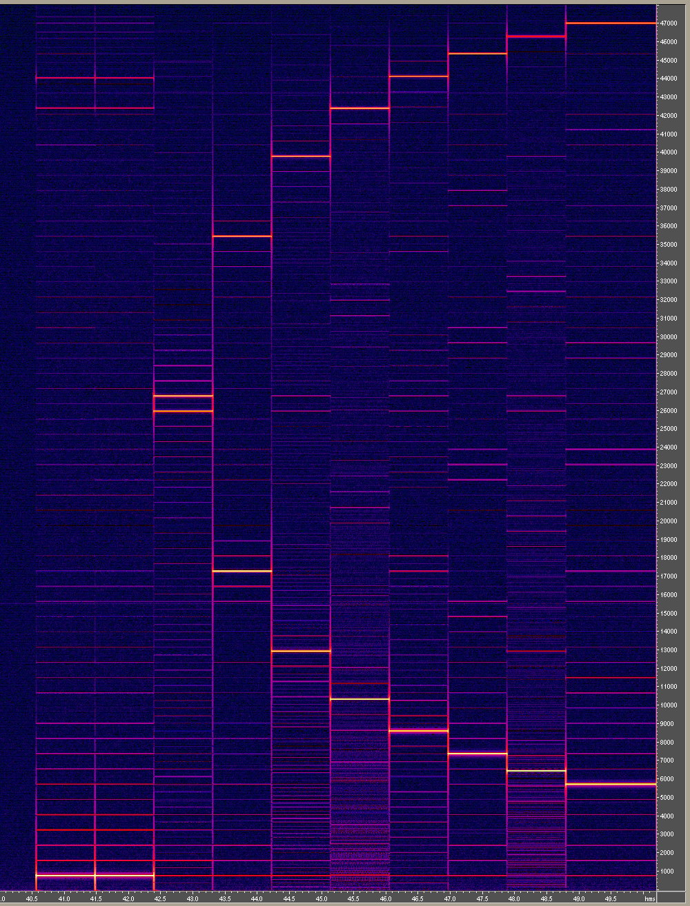
As you can see, notes 32 and 2016 (first two columns) are identical. All divisors give phantom of note 32 (825 Hz at the bottom of spectrogram), except 5 - it makes phantom of 33 (850 Hz).
And, starting from divisor 4 there is some sort of ladder steps proportionally between main and mirrored harmonics. Divisor 4 has 1 "pair of steps", divisor 5 has 2 "pairs", etc., last divisor (9) has 6 pairs.
Listening to HW we can hear the same note (excluding divisor 5) in various octaves - that prooves presenting of 825 Hz freq and its multiples.
http://shedevr.org.ru/ghost/ym2612/sweep_1000.rar
and added another demo, "mirror.asm".
I'll explain its meaning. As I mentioned it doesn't matter for YM to play frequency X or 52781-X. We know these formulas:
F-Number = 144 * freq * (2^20 / MCLOCK) / 2^(Oct - 1) / multiplier
freq = multiplier * F-Number * 2^(Oct - 1) * (MCLOCK / 2^20) / 144
MCLOCK/144 = 52781
Octave 7 gives multiplying by 64, maximum note + 1 = 2047+1 = 2048, so 2^20 / 64 / 2048 = 1048576 / 64 / 2048 = 8,
so multiplier 8, octave 7 give us frequencies up to 52781, excluding last value (it corresponds to note 2048, but highest note is 2047).
Okay, we want to see mirroring and multiplying effects and to hear low frequencies caused by these effects while our main frequencies will be high, so we won't mess "main" and "side" harmonics. So errors of low-res ADC or discrete spectrogram won't influence on our experiment and we'll hear these harmonics right in headphones.
As MASTER_FREQ corresponds to note 2048, we can operate with integer numbers.
If our freq is x, then it's multiple freqs are n*x and its mirrors are 2048-n*x. The lowest mirror will be 2048-n*x = 2048 mod x.
I want x to be multiple of some first integers (2,3,5,7...), the lowest multiple of 2..7 is 420, but 2048 mod 420 = 368, it corresponds 9 khz, it's not a good choice
If we exclude 5 then we get 84 (420/5) and this is very good number:
2048 mod 84 = 32 = 825 Hz
Mirror of 32 is 2016 and it is multiple of 2,3,4,6,7,8,9!
So I wrote this demo with dividing note 2016 by numbers from 1 to 9. And firstly it plays note 32.
Here's spectrogram (Cool Edit 1, Blackman's algorithm, 2048 bands, Range 140 dB):
As you can see, notes 32 and 2016 (first two columns) are identical. All divisors give phantom of note 32 (825 Hz at the bottom of spectrogram), except 5 - it makes phantom of 33 (850 Hz).
And, starting from divisor 4 there is some sort of ladder steps proportionally between main and mirrored harmonics. Divisor 4 has 1 "pair of steps", divisor 5 has 2 "pairs", etc., last divisor (9) has 6 pairs.
Listening to HW we can hear the same note (excluding divisor 5) in various octaves - that prooves presenting of 825 Hz freq and its multiples.
-
TmEE co.(TM)
- Very interested
- Posts: 2440
- Joined: Tue Dec 05, 2006 1:37 pm
- Location: Estonia, Rapla City
- Contact:
ok, done, looks goodGManiac wrote:No, no, thickness of lines is caused by small divisor. You should go to Settings of your program (it looks like Cool Edit 2 or higher or Adobe Audition, right?), then to "Display" or "Spectral" and choose resolution of 512..2048 bands - then lines will be thin. Also there you can increase brightness of spectrum, for 1024-2048 bands the good value is 130-140 dB.
I have Cool Edit Pro 2
http://www.fileden.com/files/2008/4/21/ ... /YM672.jpg (some stuff looks like its missing because of noise reduction which I forgot to undo).
http://www.fileden.com/files/2008/4/21/ ... /YM772.jpg
The datasheet of the chipset says the card can process 2MBytes worth of data per second... so 2000000 / 2(16bits) / 2(stereo) = 500000GManiac wrote:You mentioned Yamaha card and it's rather old, right? How can it handle 500 kHz??? while hi-end cards handle only 384 kHz with SNR 120 dB?
The card has 18bit ADC and DAC (16bits seen by outside world though). Its a ISA DMA based card so it can very well be true...
Here it is, things start getting attenuated after ~15...16KHz.GManiac wrote:And what about AFC? Please show your oscillogram, I wonder if high frequencies are filtered or not
http://www.fileden.com/files/2008/4/21/ ... /YM672.png
I don't quite know why DC offset changes... its probably because of transistors not biased optimally in the sound mod...
Mida sa loed ? Nagunii aru ei saa
http://www.tmeeco.eu
Files of all broken links and images of mine are found here : http://www.tmeeco.eu/FileDen
http://www.tmeeco.eu
Files of all broken links and images of mine are found here : http://www.tmeeco.eu/FileDen
-
Lord Nightmare
- Interested
- Posts: 19
- Joined: Sun Oct 12, 2008 10:45 pm
Ok, even if I don't understand the exact importance of them, those images look DAMN cool!
Wouldn't they look identical between MD1 and MD2 if both were sampled at the same rate? Does the samplerate have a large effect on those images? Does anyone have a ym3438/opn2c to compare to the opn2 in the md1? (the fmtowns system has an opn2c in it iirc)
LN
Wouldn't they look identical between MD1 and MD2 if both were sampled at the same rate? Does the samplerate have a large effect on those images? Does anyone have a ym3438/opn2c to compare to the opn2 in the md1? (the fmtowns system has an opn2c in it iirc)
LN
"When life gives you zombies.... *CHA-CHIK!* ...you make zombie-ade!"
-
TmEE co.(TM)
- Very interested
- Posts: 2440
- Joined: Tue Dec 05, 2006 1:37 pm
- Location: Estonia, Rapla City
- Contact:
I somehow think that YM3438 will generate things close to ASIC YM2612... the ASIC should be in CMOS (because the rest of the MD2 is CMOS)
Mida sa loed ? Nagunii aru ei saa
http://www.tmeeco.eu
Files of all broken links and images of mine are found here : http://www.tmeeco.eu/FileDen
http://www.tmeeco.eu
Files of all broken links and images of mine are found here : http://www.tmeeco.eu/FileDen
Hm, is there any way to make Yamaha chip slower? I know two ways:
1) change quartz of MD from 53 MHz to more slow
2) change frequency divider of YM2612 to more large (originally it's 7, so YM's freq is 53/7=7.6 MHz).
I don't think this is absolutely impossible, but can't say is it easy or difficult. If I could I made this by myself, but I'm strongly unfamiliar with electronics
Of course it's better to make experiments on original frequency with very powerful ADC capable of 3GHz at 16 bits, but this method will give us some advantages:
- usual sound card can replace fast ADCs (and oscilloscopes) which are pretty expensive and are often 8 bit resolution. 16 bit ones are more expensive, but it's not main problem
- 16 bit ADC must provide SNR of about 100 dB, but I don't believe that they do it. At the same time sound cards provide this SNR.
-
HardWareMan
- Very interested
- Posts: 745
- Joined: Sat Dec 15, 2007 7:49 am
- Location: Kazakhstan, Pavlodar
-
TmEE co.(TM)
- Very interested
- Posts: 2440
- Joined: Tue Dec 05, 2006 1:37 pm
- Location: Estonia, Rapla City
- Contact:
I have had nice results running YM2612 on 3.5MHz and 17MHz
I should have done some recordings...
I should have done some recordings...
Mida sa loed ? Nagunii aru ei saa
http://www.tmeeco.eu
Files of all broken links and images of mine are found here : http://www.tmeeco.eu/FileDen
http://www.tmeeco.eu
Files of all broken links and images of mine are found here : http://www.tmeeco.eu/FileDen
The main target is to record single wavefronts from YM, we know that their frequency is 317 kHz (7.67 MHz/24) and duration of 1 wavefront is 6 cycles (look at screenshots by Nemesis) and of zero point - 18 cycles. So if you want to take several samples per 1 wavefront (including silence) of YM, you should slow YM at least by 20-50 times. The good value is 158-160 times (7.60-7.67 MHz / 48 kHz) - then recording at 48 kHz speed will give us 24 "cycles" per one channel, so oscillogram from sound card will look just like in screenshots by Nemesis.
-
TmEE co.(TM)
- Very interested
- Posts: 2440
- Joined: Tue Dec 05, 2006 1:37 pm
- Location: Estonia, Rapla City
- Contact:
if the chip gets too slow, it will probably start experiencing trouble when its being written/read by much faster chip.... underclokcing controlling CPU would become necessary too I guess
Mida sa loed ? Nagunii aru ei saa
http://www.tmeeco.eu
Files of all broken links and images of mine are found here : http://www.tmeeco.eu/FileDen
http://www.tmeeco.eu
Files of all broken links and images of mine are found here : http://www.tmeeco.eu/FileDen
-
HardWareMan
- Very interested
- Posts: 745
- Joined: Sat Dec 15, 2007 7:49 am
- Location: Kazakhstan, Pavlodar
I think, access to register file is asynchronous and CPU will not have any trouble. Timers and "BUSY" flag will slow down too, so timer controlled software will slow down and software wich do not use those timers - not. Using the "BUSY" flag and timers in test ROM IMHO will works fine.TmEE co.(TM) wrote:if the chip gets too slow, it will probably start experiencing trouble when its being written/read by much faster chip.... underclokcing controlling CPU would become necessary too I guess
-
TmEE co.(TM)
- Very interested
- Posts: 2440
- Joined: Tue Dec 05, 2006 1:37 pm
- Location: Estonia, Rapla City
- Contact:
the chip probably has certain timing requirements and if the chip is made very slow, it may start missing the faster bus operations done to it.....
Mida sa loed ? Nagunii aru ei saa
http://www.tmeeco.eu
Files of all broken links and images of mine are found here : http://www.tmeeco.eu/FileDen
http://www.tmeeco.eu
Files of all broken links and images of mine are found here : http://www.tmeeco.eu/FileDen