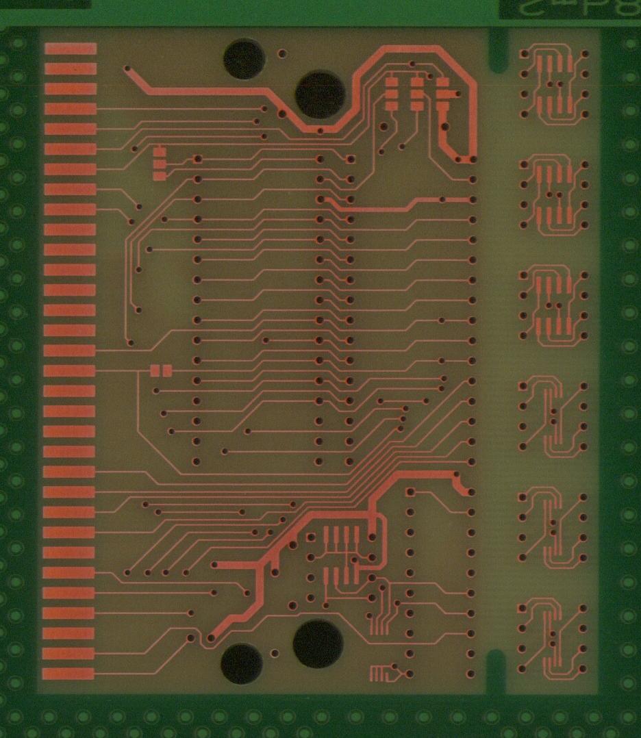
My second cart board
-
TmEE co.(TM)
- Very interested
- Posts: 2440
- Joined: Tue Dec 05, 2006 1:37 pm
- Location: Estonia, Rapla City
- Contact:
Your schematic is extremely simple, due to PAL. But if you don't use PAL, how complicated it would be ?
Mida sa loed ? Nagunii aru ei saa 
http://www.tmeeco.eu
Files of all broken links and images of mine are found here : http://www.tmeeco.eu/FileDen
http://www.tmeeco.eu
Files of all broken links and images of mine are found here : http://www.tmeeco.eu/FileDen
-
8bitwizard
- Very interested
- Posts: 159
- Joined: Sat Feb 24, 2007 11:35 pm
- Location: San Antonio, TX
EA uses three TTL chips: 74LS139 decoder, 74LS74 D flip-flop, 74LS125 tri-state buffer
Acclaim used a similar circuit with a 74LS138 decoder, but then changed to a single PAL-like chip
And using a GAL chip also let me play around with /TIME. I first tried using it as a ROM chip select, but the ROM that I have installed on that board is empty at $13000, and all I got was a page full of $FFFF. So I just now tried it with the I2C port, and it looks like writing to /TIME is done with /WR_L=0 (/OE=1 might work too, but I didn't try it), and reading is done with /OE=0. I also tried /WR_L=1 for a read, and that didn't seem to work.
So I'm probably going to use /TIME as my chip select for the I2C, just because I can.
If all you need is 256 bytes and don't mind wasting about 1800 bytes, a 28C16 EEPROM might work using /TIME and no extra chips. Or you could put a clock/CMOS RAM chip there, since /TIME supposedly got its name because someone thought a clock chip in a cartridge would be a good thing. But then you'll need a battery.
I also verified that the /TIME window is $A13000-$A13FFF. Reading memory on either side of that area causes a lock-up due to no bus acknowledge. (and no bus error circuit)
-
TmEE co.(TM)
- Very interested
- Posts: 2440
- Joined: Tue Dec 05, 2006 1:37 pm
- Location: Estonia, Rapla City
- Contact:
So you can write, but not read $A13000...$A13FFF area ? That really sucks. I'm probably not going to use EEPROMs after all unless you could provide schematic for that 3 TTL chip EA method... SRAM use is really simple, 1 logic (quad NAND)if you have al least 1 free address line (ROM size 2MB or less, or 2 (quad NAND, and 74xx74) if no free lines (i.e 4MB ROM is used).
EDIT: I read $A130F1, and my MD2 didn't halt
EDIT: I read $A130F1, and my MD2 didn't halt
Mida sa loed ? Nagunii aru ei saa
http://www.tmeeco.eu
Files of all broken links and images of mine are found here : http://www.tmeeco.eu/FileDen
http://www.tmeeco.eu
Files of all broken links and images of mine are found here : http://www.tmeeco.eu/FileDen
-
8bitwizard
- Very interested
- Posts: 159
- Joined: Sat Feb 24, 2007 11:35 pm
- Location: San Antonio, TX
I said I can both read and write with /TIME, but maybe not clear enough to be understood. I use /OE to read and /WR_L to write, just like a RAM chip would be hooked up, using /TIME as chip select instead of /CE_L. But it's only 256 bytes.
Since I made a mockup of the EA and Acclaim boards in Eagle, I should be able to get you a schematic of their I2C boards.
I just finished code that lets me read and write 24C02 and 24C16 chips, only needing to tweak a couple of constants relating to the chip size and page write size. Those two chips are particularly important because I can get them from common cartridges. NFL Quarterback Club has 24C02 and NFL Quarterback Club '96 has 24C16. And 2K is a lot of save data even for an RPG.
I'm not sure if I want to add 24C01 support. NHLPA '93 uses a 24C01, and I used its code during GAL development, but that chip doesn't support I2C device addresses, so it means one more thing to support. Right now I've got 1-byte and 2-byte address I2C support, and I'll have to add RAM support to work in an emulator, and that's all I need.
I didn't want to have to deal with the page size stuff, but it took 4 seconds to write 256 bytes to a 24C02 without page writes, and only one second with 4-byte page writes. The difference is not having to transmit three control bytes with every byte written to the EEPROM. With 16-byte page writes, 24C16 takes 3 seconds to write a full 2K bytes.
The only problem with page writes is that page sizes vary between different size chips, and sometimes with different manufacturer versions of the same size chip. So you have to change your code if you change your chip. I'll probably put I2C info at $01E0 in the header to make it easier to change.
-
8bitwizard
- Very interested
- Posts: 159
- Joined: Sat Feb 24, 2007 11:35 pm
- Location: San Antonio, TX
EA board schematic: http://xi6.com/files/genesis4/EA-P100004.gif
R1-R3 should be 4700 ohms.
There are a few things that are extra and you won't need:
* R3 is useless since SCL isn't tri-stated
* RES is unnecessary, since the bus will be reset by code anyhow
* U5 pins 4 and 13 should be connected to Vcc instead of U4 pin 6 when RES isn't used
R1-R3 should be 4700 ohms.
There are a few things that are extra and you won't need:
* R3 is useless since SCL isn't tri-stated
* RES is unnecessary, since the bus will be reset by code anyhow
* U5 pins 4 and 13 should be connected to Vcc instead of U4 pin 6 when RES isn't used
-
TmEE co.(TM)
- Very interested
- Posts: 2440
- Joined: Tue Dec 05, 2006 1:37 pm
- Location: Estonia, Rapla City
- Contact:
I don't quite get the EA method, but I'll examine it deeper at home.
I kind of like figured out a way how to use 24Cxx EEPROM during the math class in school.
It needs 74xx00, 74xx74 and 3-state bidirectional buffer with output latch (I don't know if there is such logic available).
!TIME is used to change state of SCL and EEPROM enable, and $200000...$3FFFFF is used to R/W data.
I'll post schematic later when I get home.
Mida sa loed ? Nagunii aru ei saa
http://www.tmeeco.eu
Files of all broken links and images of mine are found here : http://www.tmeeco.eu/FileDen
http://www.tmeeco.eu
Files of all broken links and images of mine are found here : http://www.tmeeco.eu/FileDen
-
TmEE co.(TM)
- Very interested
- Posts: 2440
- Joined: Tue Dec 05, 2006 1:37 pm
- Location: Estonia, Rapla City
- Contact:

I changed my previous idea. $A13xxx is used to write data, do clock, "enable/disable" EEPROM. When EEPROM is "enabled", you can read it from $200000 to $3FFFFF.
Mida sa loed ? Nagunii aru ei saa
http://www.tmeeco.eu
Files of all broken links and images of mine are found here : http://www.tmeeco.eu/FileDen
http://www.tmeeco.eu
Files of all broken links and images of mine are found here : http://www.tmeeco.eu/FileDen
How useful is the assembler? How complete is the Jaguar GPU/DSP support?8bitwizard wrote:68K assembler: http://xi6.com/files/asmx-2.0b2.zip
If you add 65816, HuC6280 and, SPC700 you could dominate WLA DX!
With those added, this could become the ultimate assembler, because it could be used across many different console systems.
-
8bitwizard
- Very interested
- Posts: 159
- Joined: Sat Feb 24, 2007 11:35 pm
- Location: San Antonio, TX
I use the assembler exclusively. But the Jaguar support was added at the suggestion of someone on AtariAge, and nobody ever actually tested it with real code. And 65816 is semi-functional, in that it doesn't do some of the addressing mode force characters in the chip manual.
Basically, it's been mostly for the things that I either used, or had some interest in. I don't think anyone else is seriously using it.
And for everything else, there's always DASM.
Back on topic, I have been doing stuff that keeps me away from it this weekend, but the first thing I want to try is to see if it works in pass-through on my Multi-Game Hunter. I really don't want to have to burn and replace two EPROM chips every time I need to test something.
-
TmEE co.(TM)
- Very interested
- Posts: 2440
- Joined: Tue Dec 05, 2006 1:37 pm
- Location: Estonia, Rapla City
- Contact:
Why not use flashes instead of EPROMs ?
Mida sa loed ? Nagunii aru ei saa
http://www.tmeeco.eu
Files of all broken links and images of mine are found here : http://www.tmeeco.eu/FileDen
http://www.tmeeco.eu
Files of all broken links and images of mine are found here : http://www.tmeeco.eu/FileDen
-
8bitwizard
- Very interested
- Posts: 159
- Joined: Sat Feb 24, 2007 11:35 pm
- Location: San Antonio, TX
Because when you try to program flash, the entire chip basically disappears and is replaced by status registers, so you have to disable interrupts and copy your programming code into RAM first. And if you screw up, the whole game could get erased. Also, trying to program two flash chips in the same memory range is a pain in the butt, because you have to program the high and low bytes separately.TmEE co.(TM) wrote:Why not use flashes instead of EPROMs ?
The reason I put flash support into my board was so that I could stick chips into the sockets that I didn't have to UV erase first. But I suppose I could make a socket adapter with a hi/lo switch that would let me use my EPROM programmer to re-program the cartridge. It's just not worth the effort, since thanks to emulators (now including copying the BIN to my hacked Xbox) there isn't much need to use an actual cartridge for testing.
So anyhow, I've finally got it working right, including a nice subroutine library that even lets me use battery RAM so that the game can work under emulators. I can also set things up to use console RAM as fake battery RAM, which is important because I normally use MacSDLMESS to run my code, and MESS doesn't have backup memory support.
-
8bitwizard
- Very interested
- Posts: 159
- Joined: Sat Feb 24, 2007 11:35 pm
- Location: San Antonio, TX
I forgot to mention the best reason... I can find chips in some common cartridges that I will be taking apart for shells anyhow.
24C01: NHLPA '93 (also in Rings of Power, but that's not common)
24C02: NBA Jam, NFL Quarterback Club
24C16: NFL Quarterback Club '96
24C65: Frank Thomas Big Hurt Baseball, College Slam
24C01: NHLPA '93 (also in Rings of Power, but that's not common)
24C02: NBA Jam, NFL Quarterback Club
24C16: NFL Quarterback Club '96
24C65: Frank Thomas Big Hurt Baseball, College Slam
-
TmEE co.(TM)
- Very interested
- Posts: 2440
- Joined: Tue Dec 05, 2006 1:37 pm
- Location: Estonia, Rapla City
- Contact:
With what do you want program the flashes that you have so much trouble ? I use my MPCP, which programs them really nicely, but very slowly since MPCP is not intelligent and QB is slow(all soft written in it). EPROMs program really fast as there are is practically no operations that need to be done to write a single byte. I'd use EPROMs but I don't have UV lamp and big EPROM chips.8bitwizard wrote:Because when you try to program flash, the entire chip basically disappears and is replaced by status registers, so you have to disable interrupts and copy your programming code into RAM first. And if you screw up, the whole game could get erased. Also, trying to program two flash chips in the same memory range is a pain in the butt, because you have to program the high and low bytes separately.
Mida sa loed ? Nagunii aru ei saa
http://www.tmeeco.eu
Files of all broken links and images of mine are found here : http://www.tmeeco.eu/FileDen
http://www.tmeeco.eu
Files of all broken links and images of mine are found here : http://www.tmeeco.eu/FileDen
Re: My second cart board
Are these boards you intend to produce, similar to the Pixel Past (http://www.pixelspast.com/) boards?

-
8bitwizard
- Very interested
- Posts: 159
- Joined: Sat Feb 24, 2007 11:35 pm
- Location: San Antonio, TX
Re: My second cart board
Yes. And if you're interested in seeing them produced sooner rather than later, email me at bruce@fanboy.net and I'll start work on making a production run.cdoty wrote:Are these boards you intend to produce, similar to the Pixel Past (http://www.pixelspast.com/) boards?
At this point, all I really need to fix is to keep the ground plane fill away from the solder pads. The GAL and the EEPROM support code are already finished.
Basic specs are:
* Fits in both Sega and EA cartridge shells
* Supports two 8-bit ROMs, either EPROM or Flash, up to 4 megabits each for a total of 1 megabyte (8 megabit 27C080 EPROMs should work if you can find them in a DIP package)
* Solder jumper pads are provided to select the different pinouts for EPROM vs Flash ROMs
* Supports an I2C EEPROM for game saves (DIP, SOIC or TSOP), with I2C I/O source code available
* If I2C is not used, a solder jumper pad can be used in place of the GAL chip
Note that the I2C hardware is basically not compatible with any of the less than a dozen Genesis games which used I2C save memory, but those few games are not worth making repros of anyhow. I2C was chosen as an alternative to battery RAM for new games, by replacing a large RAM chip, battery, and battery monitor chip with one small chip; and using one decode chip instead of at least two.
Of course you should keep in mind that these boards are by necessity twice as big as the PP 2600 boards, and board cost is generally related to area size. I can probably sell them for $8 or so with a medium-quantity production run.
FYI, I made the Atari 7800 boards which recently got used for the Missing in Action release:
http://atari7800.net/mini-ultra/
http://www.atariage.com/forums/index.ph ... pic=107756