My second cart board

For hardware talk only (please avoid ROM dumper stuff)
8bitwizard
Very interested
Posts: 159
Joined: Sat Feb 24, 2007 11:35 pm
Location: San Antonio, TX

My second cart board

Post by 8bitwizard » Wed Mar 28, 2007 5:14 pm

Image

big picture: http://xi6.com/files/genesis4a-2007-03-28-uvcuring.jpg

I'll should get the boards sometime next week.

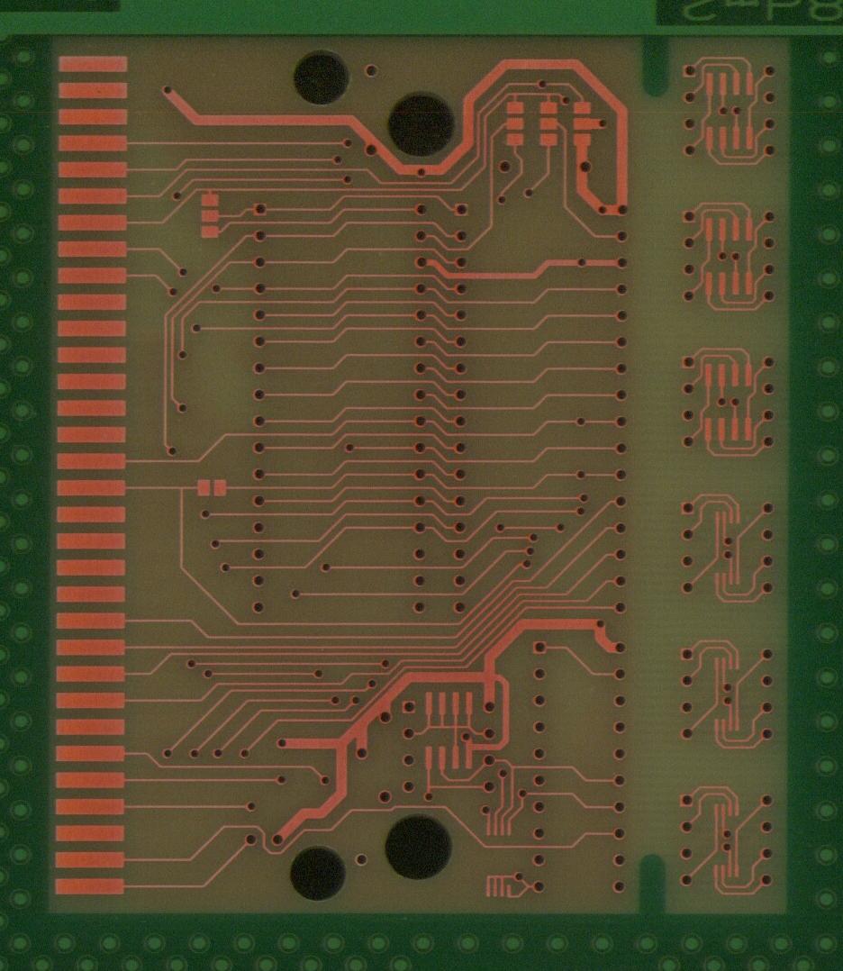
The stuff on the right is a bunch of 8-pin serial EEPROM adapter boards that I paneled onto a copy of my design before sending it off to be made. I'm making four boards, so that should give me a dozen each of the adapters at a cost of less than two for a dollar.

This board goes up to 8 megabits (1 megabyte), or twice that if you can find 27C080 type chips. That was the point where everybody switched to surface-mount flash, so it gets a bit tricky to put more into a standard size cart board. For really small stuff (128K bytes or less) you can use a pair of 27512 or 27256 chips.

The jumper pads are for 28 vs 32 pins, EPROM vs Flash, and one more to bypass the EEPROM mapper chip when the EEPROM isn't installed. I also set up the TSSOP EEPROM pad to have its address pins separately grounded through a via so that I can have two chips at different I2C addresses with a little rewiring.

Also note the holes cut for both regluar Sega carts and EA carts. I later looked at Accolade carts, but their holes were in an incompatible location. Doing a quick check by holding a board in front of my screen shows that the EA holes are in the right place, and the Sega holes are either in the right place or a little too high.

TmEE co.(TM)
Very interested
Posts: 2440
Joined: Tue Dec 05, 2006 1:37 pm
Location: Estonia, Rapla City
Contact:

Post by TmEE co.(TM) » Thu Mar 29, 2007 5:22 am

This is awesome
Mida sa loed ? Nagunii aru ei saa ;)
http://www.tmeeco.eu
Files of all broken links and images of mine are found here : http://www.tmeeco.eu/FileDen

8bitwizard
Very interested
Posts: 159
Joined: Sat Feb 24, 2007 11:35 pm
Location: San Antonio, TX

Post by 8bitwizard » Fri Apr 20, 2007 3:40 am

I finally got a chance to put one together today. They came in a few days ago, and right away I clipped off the adapter boards and tested it for fitting in a cartridge shell. It seemed to be okay in both Sega and EA shells. Then I took one of the SOIC adapter boards, mounted the EEPROM from a dead Xbox, read the chip, and was able to use that to recover the key to unlock the hard drive. Next time I panelize something like that, I'll remember to put a couple of drills along the break lines.

The big problem I had today was that for this board I had discovered how to do polygon fills in Cadsoft Eagle (the trick was learning that the "ratsnest" button generated the actual polygon fill, and that I had to name the polygon fill). But it used the mimimum spacing distance for the fill, so all my solder pads were 6 mils from the monster ground plane. This made soldering much more tricky, and I had to test for and fix shorts to ground. For my next run of boards I'll probably use multiple polygons to keep the ground plane away from the IC pins.

The first thing I did was make sure that the EPROM part worked, so I jumpered the GAL bypass and sure enough a game worked. Then I removed the solder jumper, programmed a 16V8, and it didn't work. So I started to make a simplified 16V8 programming file, and discovered that I had swapped a couple of pins at the last moment when routing the board, but forgot to update the 16V8 programming file. Oops.

After reprogramming the 16V8, the game started up. Now I need to write some code to test reading the I2C EEPROM.

For what it's worth, there seem to be at least three different ways that EEPROMs were used:

* EA (the one I chose) has the ROM at 000000-1FFFFF, and the EEPROM access at 200000-2FFFFF, with SDA on D7 and SCL on D6. The nice thing about this is that if you read it with MOVE.B, it sets the N bit such that you can BPL/BMI right away.

* One Acclaim method has ROM at 000000-1FFFFF, and EEPROM access at 200000-3FFFFF, SCL/SDA write on D1/D0, and SDA read on D1.

* The other Acclaim method uses a custom chip that only uses A20, A21, D0 and other signal lines. I won't know how it works without looking at the game code for it.

I'm also considering using /TIME to access the EEPROM, if only to see if I can get it to work.

As for what to do about emulators, I plan to put in support for standard RAM and auto-detect for it. If the RAM isn't found, it'll use the EEPROM instead.

TmEE co.(TM)
Very interested
Posts: 2440
Joined: Tue Dec 05, 2006 1:37 pm
Location: Estonia, Rapla City
Contact:

Post by TmEE co.(TM) » Fri Apr 20, 2007 5:22 am

Great work :D .

My idea to connect an EEPROM is that you put !TIME to SCL and Dx to SDA. I don't know much about EEPROMs though, and I guess it will be pretty slow to read/write them on MD (i.e 9(?) read/write operations to write/read any data).

Why would you need a GAL ? For I2C EEPROM ?

Your board doesn't seem so tight that you would have trouble with soldering... TSOP adaptors on my flashcart were pains-in-the-@$$
Mida sa loed ? Nagunii aru ei saa ;)
http://www.tmeeco.eu
Files of all broken links and images of mine are found here : http://www.tmeeco.eu/FileDen

8bitwizard
Very interested
Posts: 159
Joined: Sat Feb 24, 2007 11:35 pm
Location: San Antonio, TX

Post by 8bitwizard » Fri Apr 20, 2007 1:09 pm

What you're thinking won't work because you have to have a latched output port to talk with I2C.

The GAL chip does all the decoding, replacing four or five or more TTL chips, plus it has the latches needed for SCL and SDA. And they are reprogrammable, so I can take it out, reprogram it, and make it do something different, or just fix a bug in the decoding.

And you are only looking at the front of the board. Imagine the blank area covered a with ground plane and only a hairline between the ground plane and the small circle pad around the pin. I also had a short from the soldering iron wiping across some adjacent traces. That alone took me about 15 minutes to trace down.

TmEE co.(TM)
Very interested
Posts: 2440
Joined: Tue Dec 05, 2006 1:37 pm
Location: Estonia, Rapla City
Contact:

Post by TmEE co.(TM) » Sat Apr 21, 2007 9:12 am

8bitwizard wrote:What you're thinking won't work because you have to have a latched output port to talk with I2C.
I opted for 24Cxx not I2C types, I guess it should work. I believe, that I won't need any extra logic.
8bitwizard wrote:The GAL chip does all the decoding, replacing four or five or more TTL chips, plus it has the latches needed for SCL and SDA. And they are reprogrammable, so I can take it out, reprogram it, and make it do something different, or just fix a bug in the decoding.
I have got handful of GALs and PALs form old PCs, I have no tools to make "program" for them but I have hardware to program them.
8bitwizard wrote:And you are only looking at the front of the board. Imagine the blank area covered a with ground plane and only a hairline between the ground plane and the small circle pad around the pin. I also had a short from the soldering iron wiping across some adjacent traces. That alone took me about 15 minutes to trace down.
I imagine it, I faced same trouble when I soldered flashes onto the adaptors. Next time I make the gaps between 2 traces more than quarter of a millimeter :wink:
Mida sa loed ? Nagunii aru ei saa ;)
http://www.tmeeco.eu
Files of all broken links and images of mine are found here : http://www.tmeeco.eu/FileDen

8bitwizard
Very interested
Posts: 159
Joined: Sat Feb 24, 2007 11:35 pm
Location: San Antonio, TX

Post by 8bitwizard » Tue Apr 24, 2007 5:12 pm

TmEE co.(TM) wrote:I opted for 24Cxx not I2C types, I guess it should work. I believe, that I won't need any extra logic.
Huh? 24Cxx is I2C. Maybe you meant 28Cxx?

TmEE co.(TM)
Very interested
Posts: 2440
Joined: Tue Dec 05, 2006 1:37 pm
Location: Estonia, Rapla City
Contact:

Post by TmEE co.(TM) » Wed Apr 25, 2007 5:42 am

Oh yeah you're right. I messed it up with something else. Anyway I'm going to test out 24Cxx. First I try it in my MPCP http://www.hot.ee/tmeeco/DWNLOADS/MPCPSHIT.RAR and then I'll see if I can get it working in my MD.
Mida sa loed ? Nagunii aru ei saa ;)
http://www.tmeeco.eu
Files of all broken links and images of mine are found here : http://www.tmeeco.eu/FileDen

TmEE co.(TM)
Very interested
Posts: 2440
Joined: Tue Dec 05, 2006 1:37 pm
Location: Estonia, Rapla City
Contact:

Post by TmEE co.(TM) » Thu Apr 26, 2007 7:56 am

$h1T !!! You were right, using just !Time signal wouldn't work. If START and STOP conditions mustn't be issued like they have to, it would work.
Mida sa loed ? Nagunii aru ei saa ;)
http://www.tmeeco.eu
Files of all broken links and images of mine are found here : http://www.tmeeco.eu/FileDen

8bitwizard
Very interested
Posts: 159
Joined: Sat Feb 24, 2007 11:35 pm
Location: San Antonio, TX

Post by 8bitwizard » Tue May 08, 2007 8:06 pm

I finally figured out what my problem was with getting the I2C working. I was using my own PAL assembler program and it had a subtle bug where a registered term would silently become unregistered if you gave it a ".OE" term. And that's exactly what I did. I didn't figure it out until I started adding test vectors for SDA and SCL.

So now I have successfully read the EEPROM that I pulled from an NHLPA '93 cartridge. For what it's worth, that is an Atmel 24C01, which isn't strictly I2C. It uses the I2C protocol, but not I2C addressing. The Atmel 24C01A and other manufacturers' 24C01 chips use a device address. But I knew this and I was using was using the code from NHLPA '93 anyhow.

TmEE co.(TM)
Very interested
Posts: 2440
Joined: Tue Dec 05, 2006 1:37 pm
Location: Estonia, Rapla City
Contact:

Post by TmEE co.(TM) » Wed May 09, 2007 7:36 am

Can you post any schematics of "official" EEPROM accessing logic ? I've come up with several ideas, but all required 3 logic chips, I almost could have made one with 2 chips, but then I couldn't have 4MB ROM... I'd post them if you like.
Mida sa loed ? Nagunii aru ei saa ;)
http://www.tmeeco.eu
Files of all broken links and images of mine are found here : http://www.tmeeco.eu/FileDen

8bitwizard
Very interested
Posts: 159
Joined: Sat Feb 24, 2007 11:35 pm
Location: San Antonio, TX

Post by 8bitwizard » Wed May 09, 2007 2:44 pm

It's not in an easy to post format right now, but I can work on it. One big problem is that it's a Cadsoft Eagle project, and I just stick stubs of nets to the IC pins in the schematic editor, so they aren't labeled. (And the "official" stuff, being what I traced out, is a bunch of hand drawings on paper, and more Cadsoft Eagle projects to ensure that I got things fully traced out.)

I will also need to post the updated version of my GAL assembler along with the equations, since I fixed a long-known limitation it had with registered feedback terms. (for some reason, probably because "PALs did it that way", all registered outputs on all GALs use the inverted /Q output from the latch for the feedback term)

Also be aware that I hooked up a lot more pins to the GAL chip than I actually used. I basically hooked up anything that I thought I might need to use or experiment with, like /TIME. I was also at first trying to use the /RES pin to reset the flip-flops to a known state, even though I knew it wasn't really necessary, because the EA board did it that way. That got removed when I couldn't figure out why the SDA line wouldn't flip, which was because of the problem in my GAL assembler.

Shiru
Very interested
Posts: 786
Joined: Sat Apr 07, 2007 3:11 am
Location: Russia, Moscow
Contact:

Post by Shiru » Wed May 09, 2007 2:58 pm

8bitwizard wrote:One big problem is that it's a Cadsoft Eagle project, and I just stick stubs of nets to the IC pins in the schematic editor, so they aren't labeled.
Is that a really big problem?:) I don't think you have too much wires in buses, so all you need is click ABC icon ('Label') and then click every wire in bus (only where you need to label it). It will take only some minutes.

TmEE co.(TM)
Very interested
Posts: 2440
Joined: Tue Dec 05, 2006 1:37 pm
Location: Estonia, Rapla City
Contact:

Post by TmEE co.(TM) » Wed May 09, 2007 3:19 pm

I will not use 24Cxx EEPROMs, my ideas won't work... Now I'm going to try 93Cxx EEPROMs. If these chips would have !CE line, it would make my (and everyone's elses) life lot easier.
Mida sa loed ? Nagunii aru ei saa ;)
http://www.tmeeco.eu
Files of all broken links and images of mine are found here : http://www.tmeeco.eu/FileDen

8bitwizard
Very interested
Posts: 159
Joined: Sat Feb 24, 2007 11:35 pm
Location: San Antonio, TX

Post by 8bitwizard » Wed May 09, 2007 6:02 pm

Hmm, I never noticed the ABC before. But I already went ahead and did text labels and got it converted to a GIF file.

http://xi6.com/files/genesis4/

PAL assembler: http://xi6.com/files/palwiz-1.1.zip
68K assembler: http://xi6.com/files/asmx-2.0b2.zip

Post Reply